
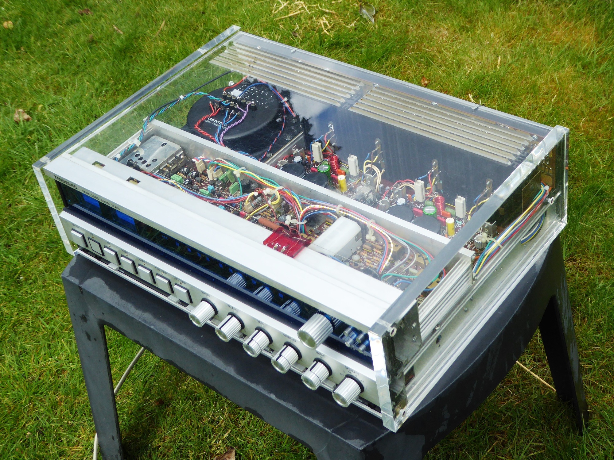
Acrylic Tandberg tr-2075 refurbishment 2022
Selling it on the internet market during 2022, the buyer appeared to be the very same person I bought my woodcase TR2075 from, which I refurbished during 2016! In this case, the very reason for selling it was still having one more TR2075 to refurb....
Gemakshalve is deze pagina verder in het Engels geschreven.
![]() This page was written using English language only.
This page was written using English language only.
This Tandberg TR2075 was sold to me as needing "some cleaning only", but "as expected", it did not work.
Symptom was "no sound", the problems encountered are described below.
It looks, the previous owner did some unsuccessful attempts, the perfect scenario to pick up this receiver not TOO expensive.
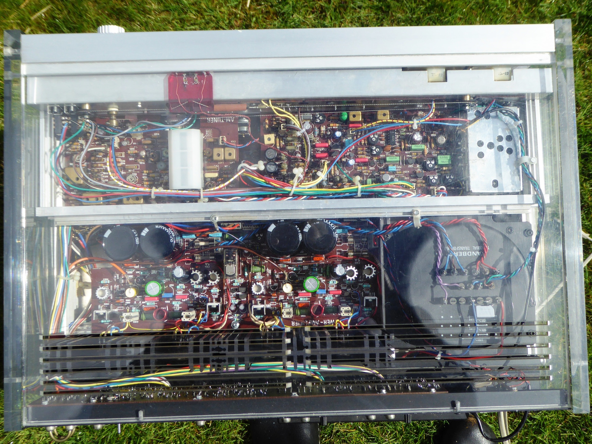
Apart from the AM tuner getting only a few new capacitors, most circuit cards of this receiver were rigorously reworked, this was needed.

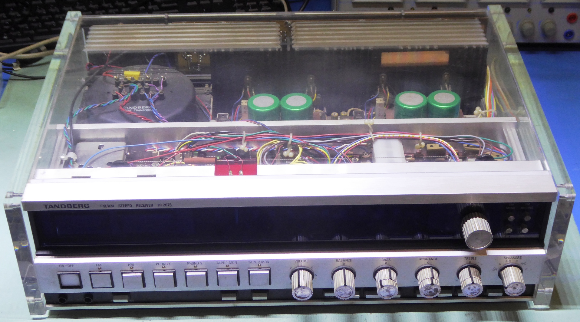
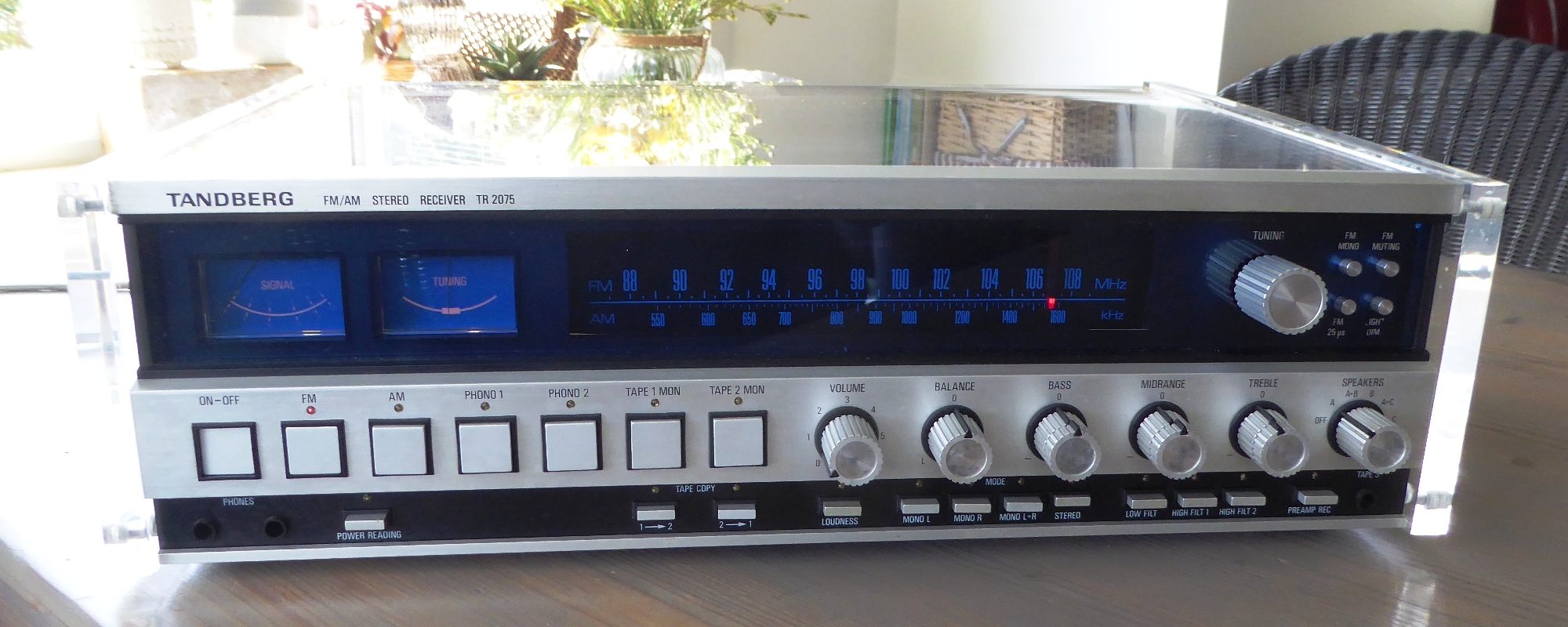
The Receiver as it was. Apart from being dirty, it seems in pretty good physical shape.
The deteriorated front of the aluminium knobs is quite normal for these receivers (and TR2055 also).
Later ones, like the TR2075MKII and the TR2080 have other knobs, which do not deteriorate.
The Tuner assembly
As in my other TR2075 resto, I did put new Festoon lamps in it. I also glued some shiny aluminium tape in the housing to get more reflection.
Because of all the dirt, I took the risk of replacing all the trimming potentiometers, most are the black Piher type, now.
Additionally, all electrolytic capacitors were replaced by capacitors assumed suitable.
The power regulator transistor and 120 Ohms accompanying resistor were replaced for longevity reasons, the 1 Watt 330 Ohms resistor too as there were signs of discoloring by the dissipated power.
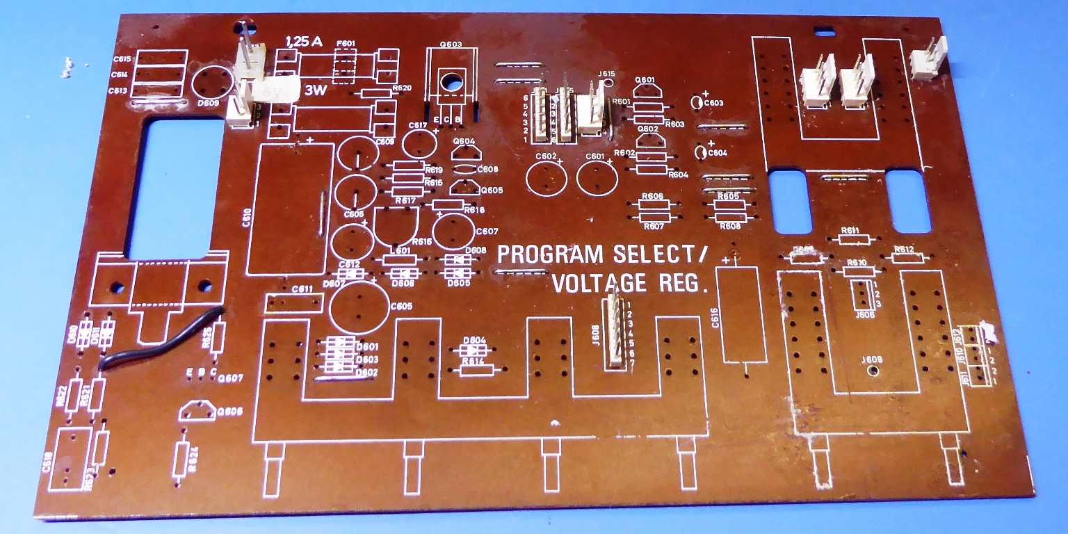
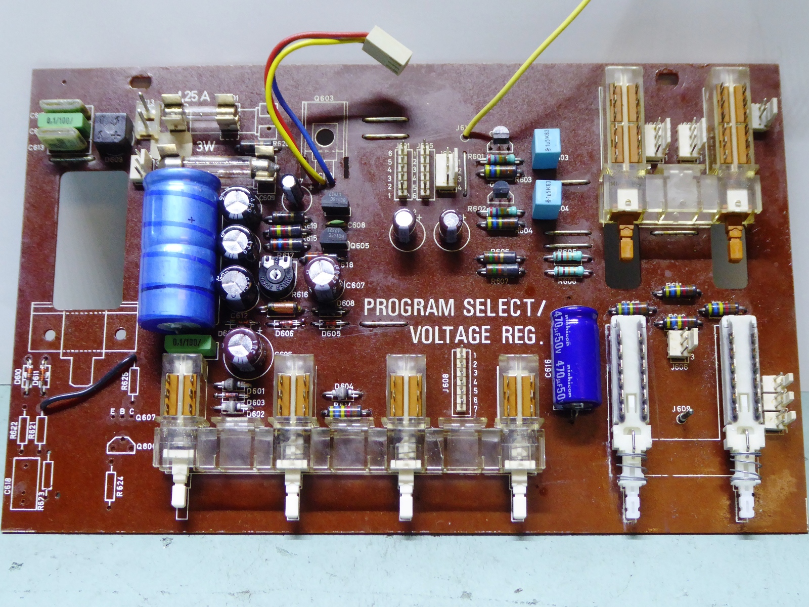
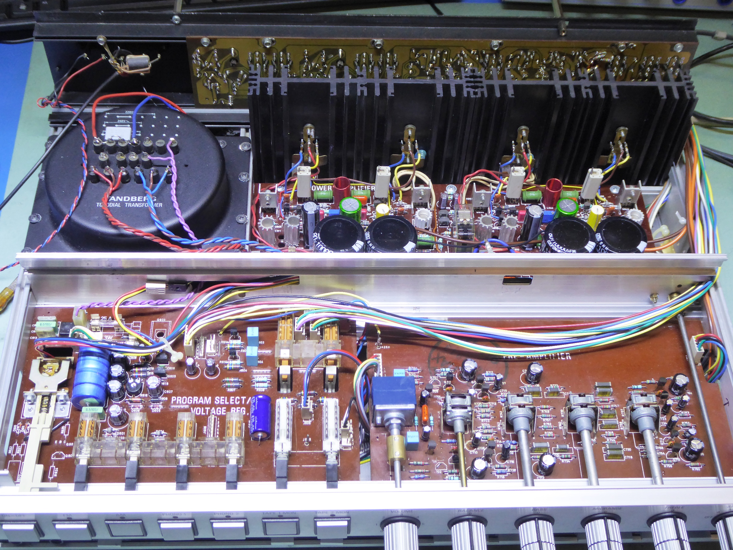
Program Select / Voltage regulator board / Power supply
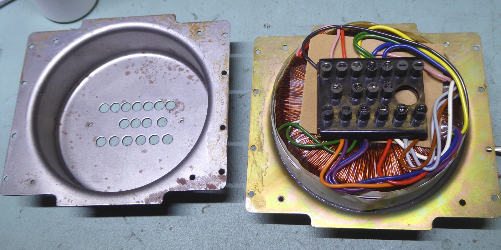
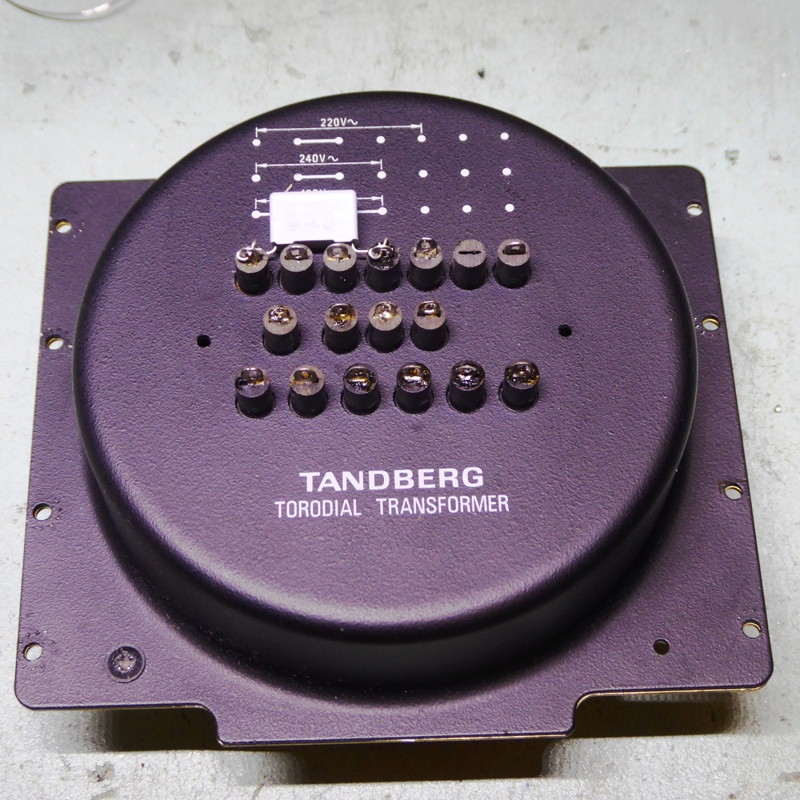
The transformer has one wire exchanged from the 220V setting to the 240 Volts setting, accompanied by a new "snubber" safety capacitor.
It was opened up, just to see how the innards look. It appears it is potted, so one can not take it out of the enclosure, and probably this helps against transformer hum.
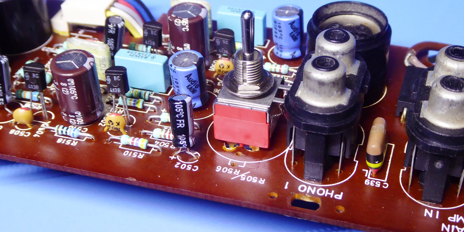
The regulator / program select board was not in a good shape, it had two defective tape selector buttons.
The left Tape selector was yellowish and sticky (did not come out of position) and full of deterioration due to contact cleaner use, it appeared to be half of the original part.
The one on the right did have non-functional switch contacts, giving the alike result.
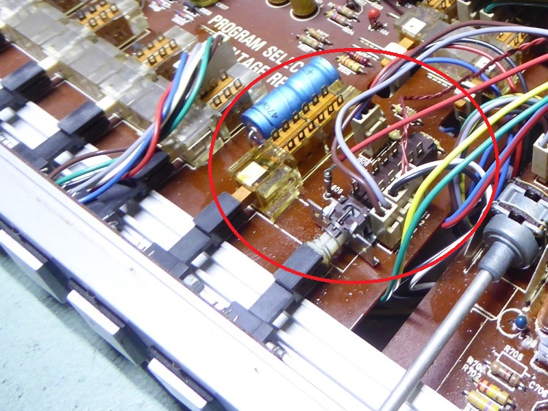
Fortunately, two new Shadow switches which were adaptable for single use were available and put in.
This circuit card also contains the big Frako yellow capacitor, which is suspect to be unreliable according forums information, it sometimes seems to fail shorted.
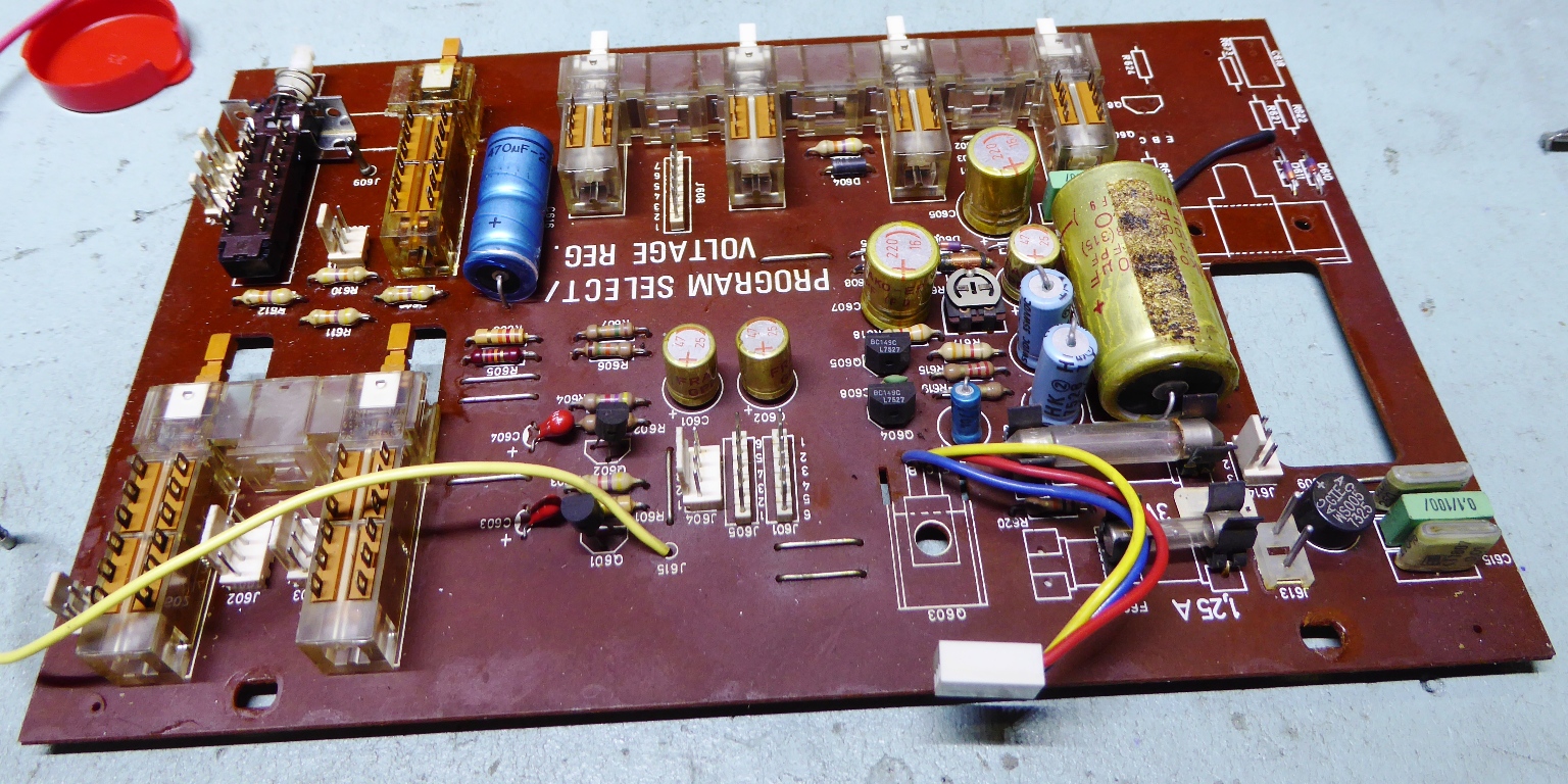
The electrolytic capacitors were tested, four were good, six (on the right of the picture right below) were bad!
The very little blue Philips was the worst, somehow my Quadtech 1715 LCR meter was unable to display a stable picture of the capacitance.
Such is a very good reason to justify a "recap".
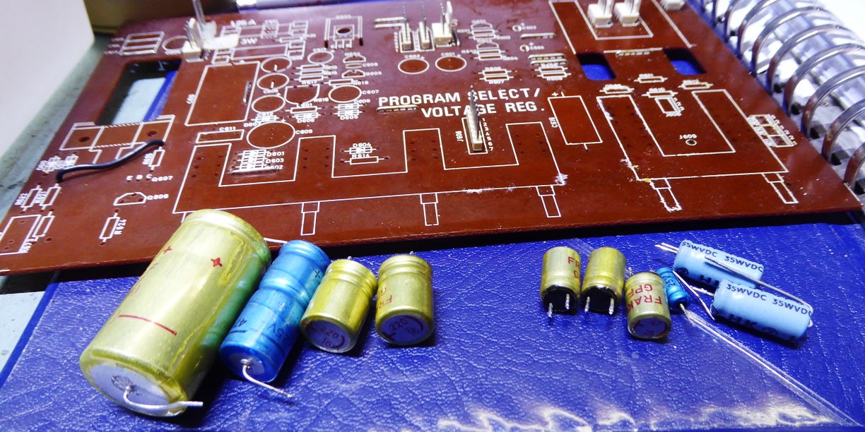
I repopulated the board using suitable components. The big smoothing capacitor is 2200 microfarads now, instead of 1000. Others may have a raised capacitance also, and the little Tantalum capacitors were replaced by Siemens blue film capacitors.
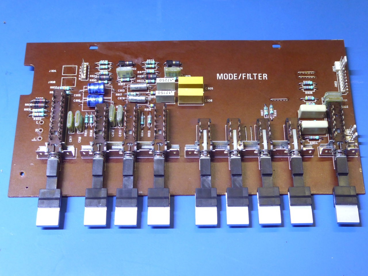
Mode/filter board
Several selections are done on the mode/filter board.
Funny is always Tandberg seemed to use "same type BUT a little bit different" components, many times.
This mode/filter board is an example, it uses a BC549 transistor for one channel, and a BC413 for the other.
Some specific resistor is from another brand, as is some capacitor, a green versus a yellow one.
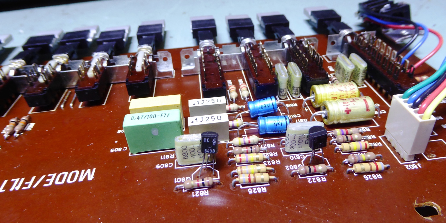
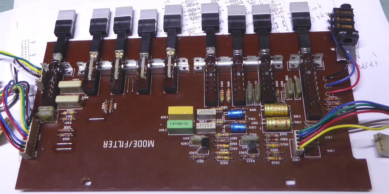
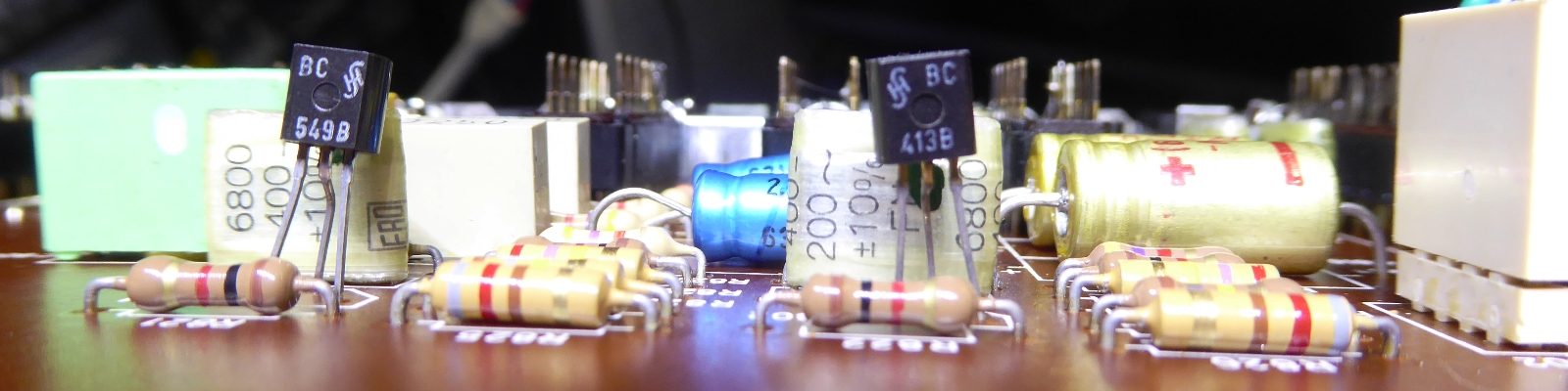
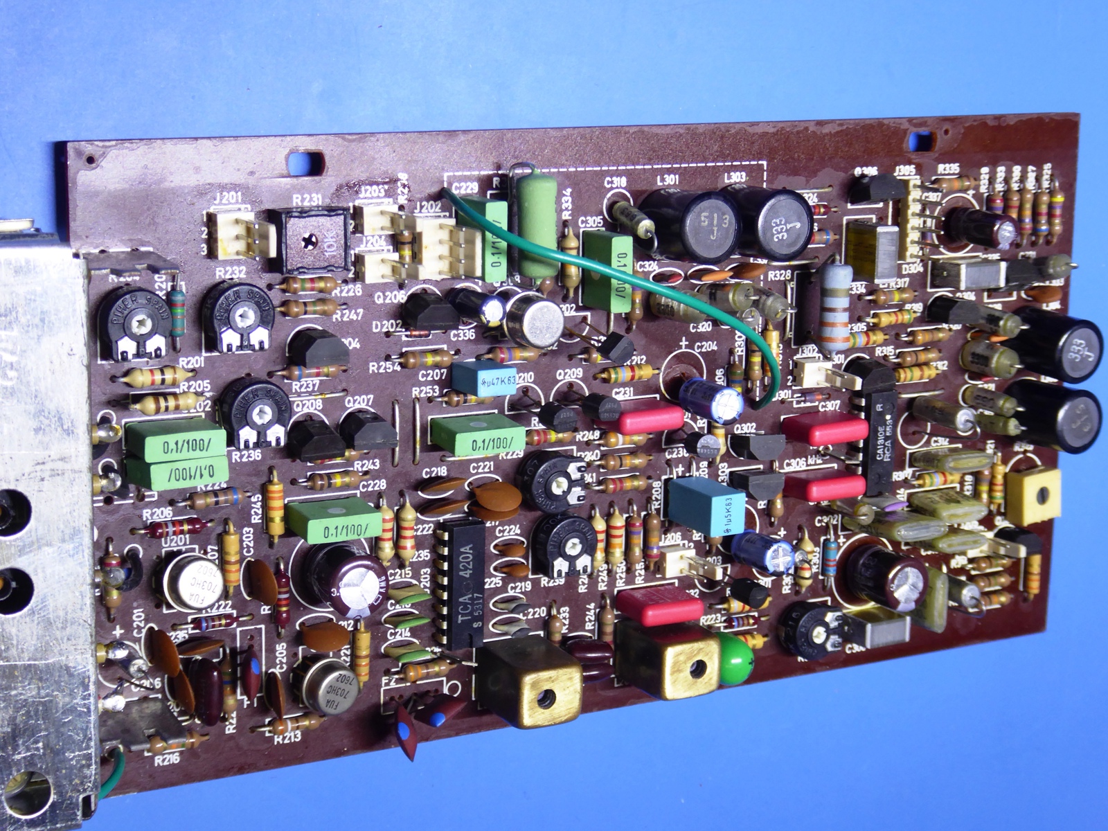
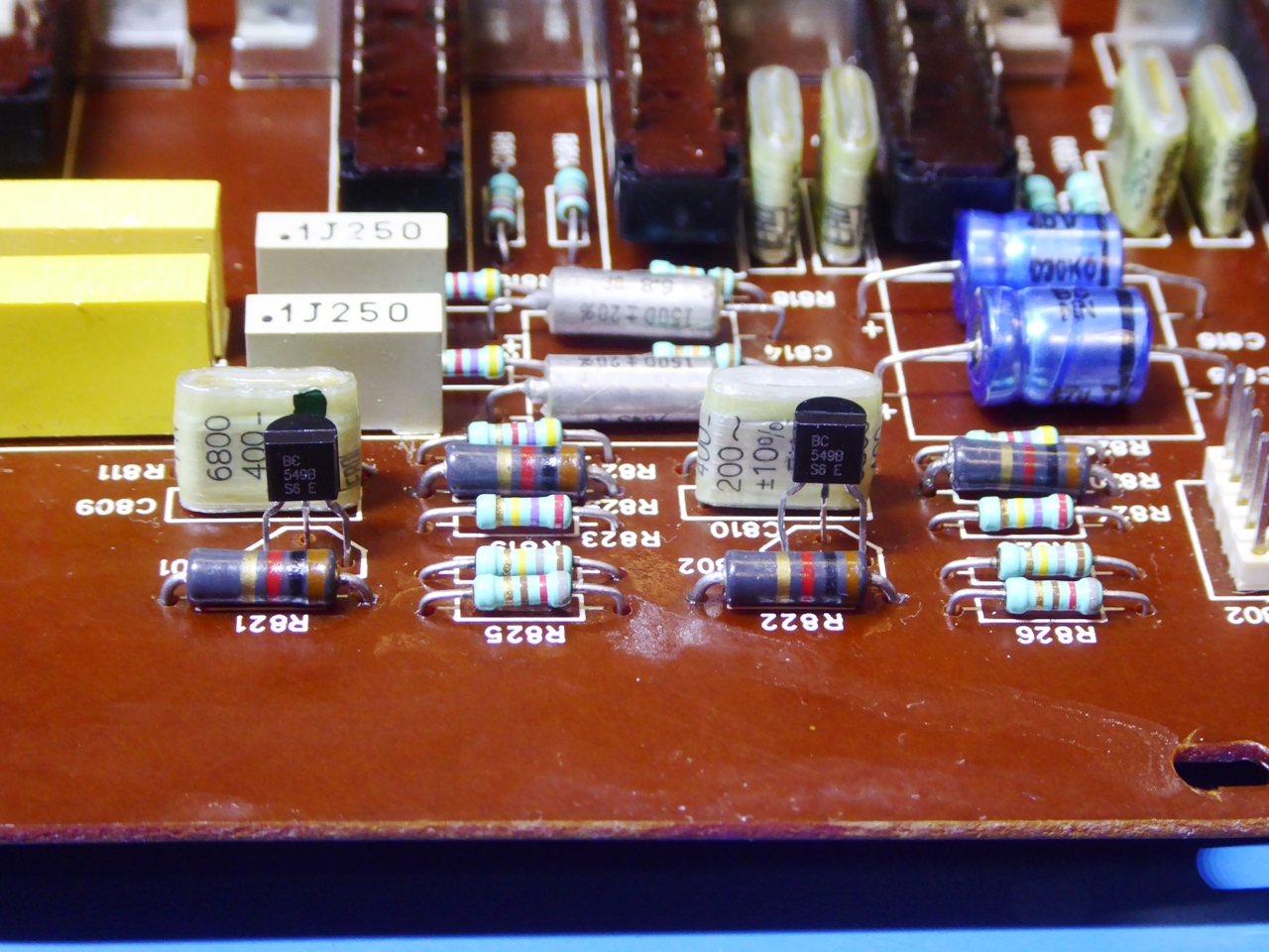
Also de mode/filter board was renewed:
Notice the smaller new resistors on the picture down right are Philips MRS25, the bigger ones are CGW glass-body resistors, comparable to RN60D style milspec resistors.
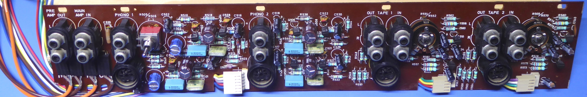
RIAA input board
The RIAA board was rebuilt, but during test, it appeared to have a big output difference between the channels of the Phono 1 section.
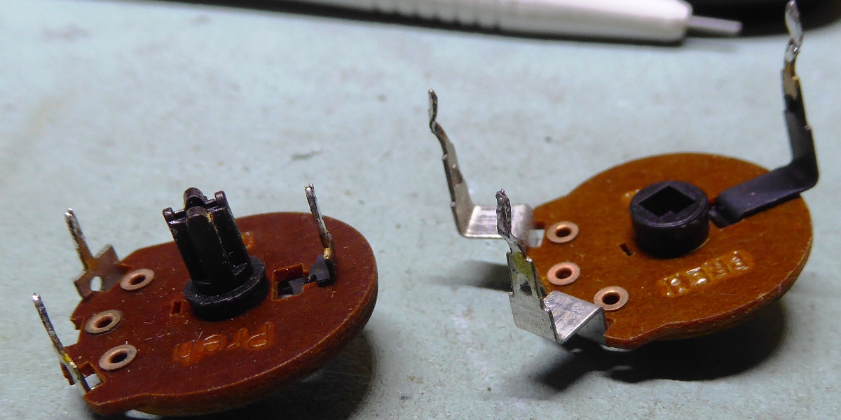
The reason appeared to be the rear accessible stereo trimming potentiometer.
The halves of these potentiometers are supposed to be 1 kilo-ohms each, but practically, one was 850 Ohms and one over 1200 Ohms.
As these are obsolete and there was no way to replace them, a solution was found by using a switch having a mid position, and a pair of resistors.
Instead of having a variable range, now there are three possibilities, a 2mV, 4 mV and 10 mV sensitivity. Additionally, having a potentiometer in the amplifier feedback loop, was not exactly good for signal to noise, so maybe performance is better compared to the original when the potentiometer was still good.
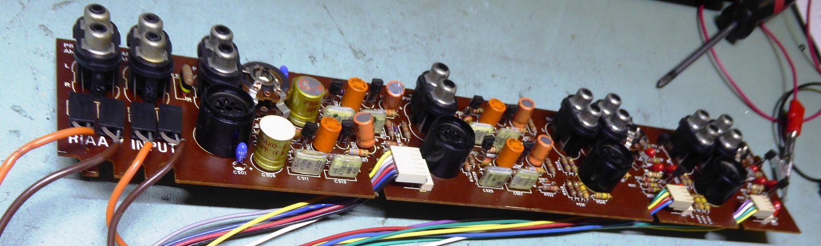
It should be noted, on this card, all resistors are (Philips) metal film ones, now.
Although I replaced all electrolytic capacitors, no defective ones were found. Part of the greenish film capacitors were changed out, the four 22 nanofarad ones, because they deviated too much from each other. They are in the RIAA filter, influencing the frequency-dependent gain.
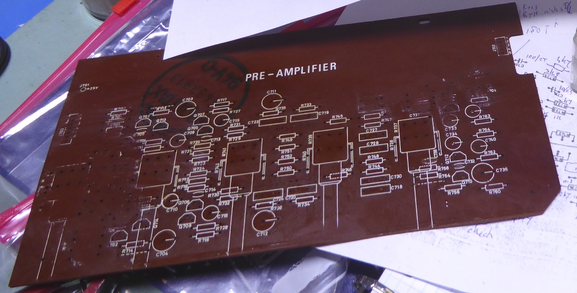
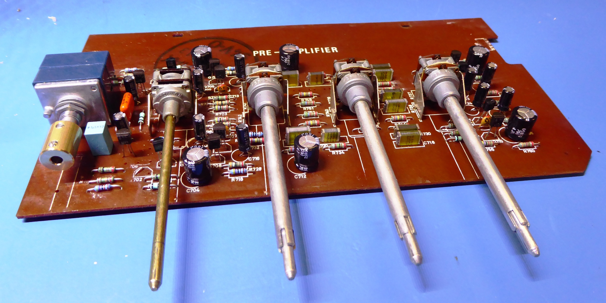
The pre amplifier.
The preamplifier potentiometers were still in good shape, except for the volume potentiometer being totally unusable.
Such potentiometers are not to be found, anymore.
Several possible replacements were bought, the most luxury one was an Alps, which was found to be suitable and it was mounted.
This potentiometer does not have loudness circuit attachments, so unfortunately, the loudness button is inop from now on.
A 6mm to 4 mm adapter piece was mounted, and the old potentiometer shaft was cut off and reused by attaching it to the adapter.
Although the new potentiometer is much bigger, only one capacitor had to move up, a little. I drill holes as necessary whenever practical.
The whole preamp card was refurbished.
It should be noted, the old potentiometer routed the ground signal through its mounting metal, so this should be wired again.
Using IPA to clean the card, immediately the text was dissolved, so cleaning of the cards seems risky.
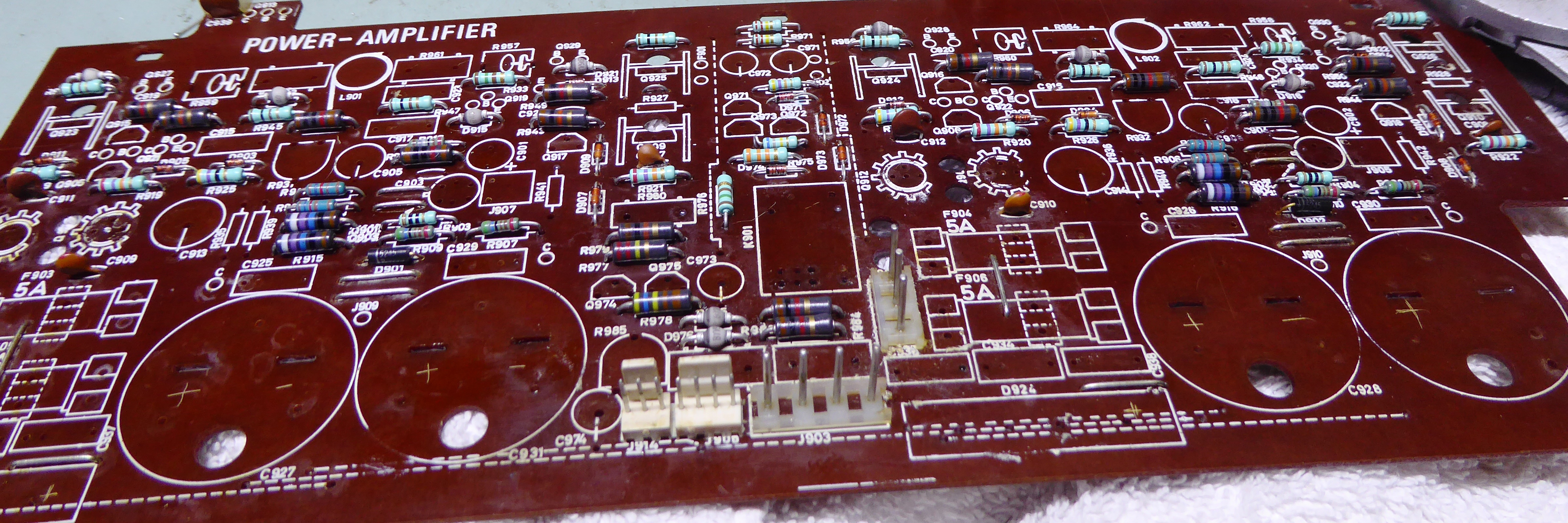
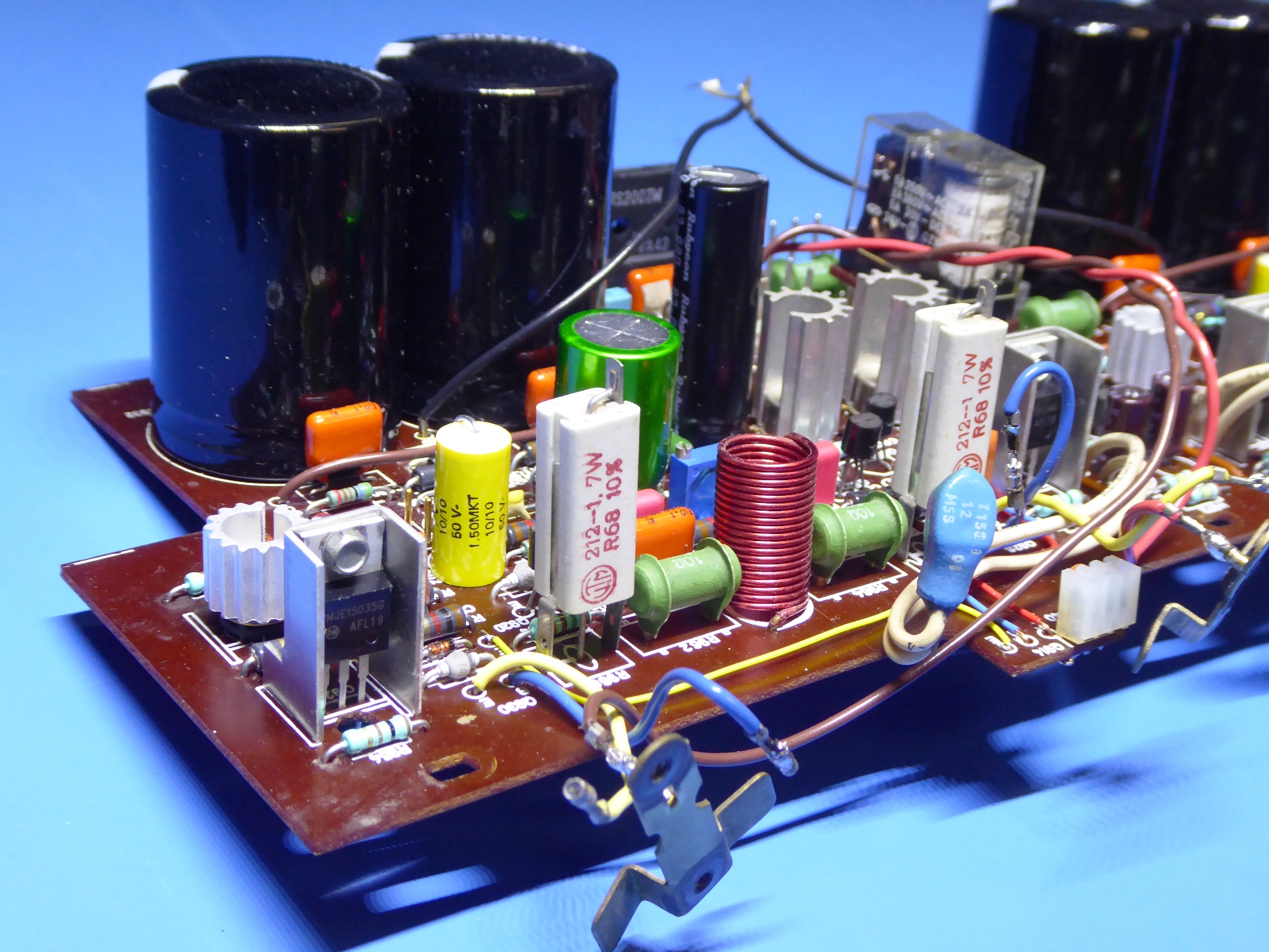
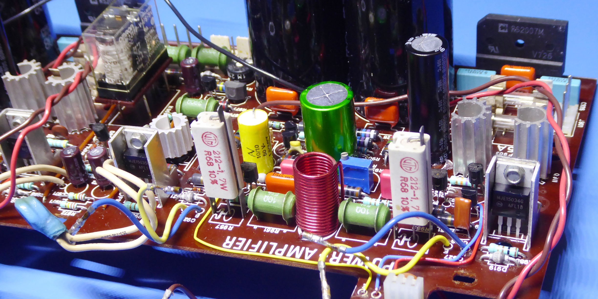
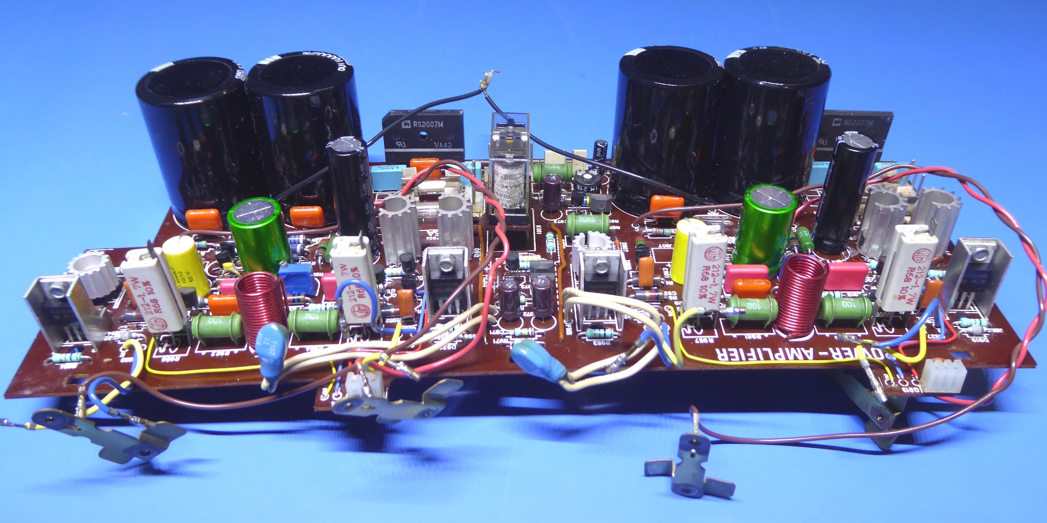
The power amplifier circuits.
The main amplifier was still operational. It was very dirty and it was too distracting to have such in a showpiece as this receiver is.
Noteworthy is, unlike the newer TR2075-MKII and TR2080, the "Mark 1" like this one has separate cables and rectifiers to feed the amplifiers.
It was decided to take it apart totally, and refurbish it.
One of the green BY127 diodes had a different forward voltage compared to an other one, they were all replaced.
A main power output transistor had somewhat low HFE, one of the driver transistors also, so the driver and power transistors of both channels were replaced.
The electrolytic capacitors were exchanged, the bridge rectifiers to accomodate possible higher power-on current.
I did this, hoping to make the amplifier as reliable as possible.
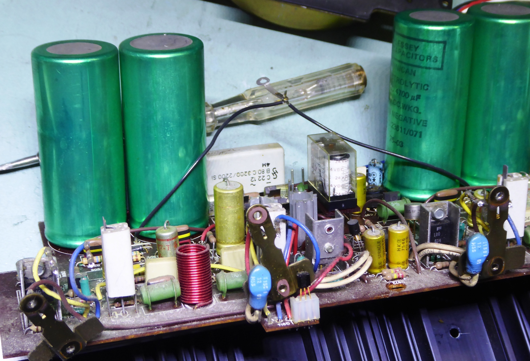
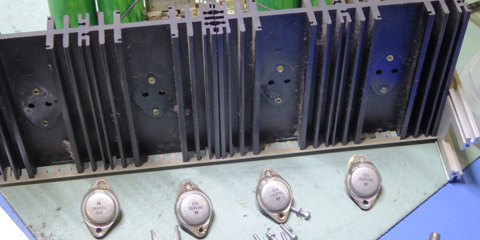
The power output transistors were replaced by MJ15001 and MJ15002, the driver transistors by MJE15034 and MJE15035
The resistors are a mix of my favorite real glass body Corning Glassworks metal film ones again, and Philips MRS resistors
An "audiophile" bipolar decoupling capacitor was used for the negative feedback DC decoupling loop. It is green, it looks nice and it was available, whether it is better or not is subject of doubt and/or debate ;-)
Ga naar Gerards page / go to Gerards page ---->>> ![]()