Ga naar Gerards page / go to Gerards other pages ---->>> ![]()

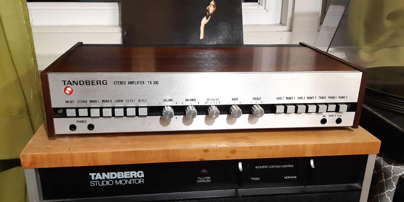
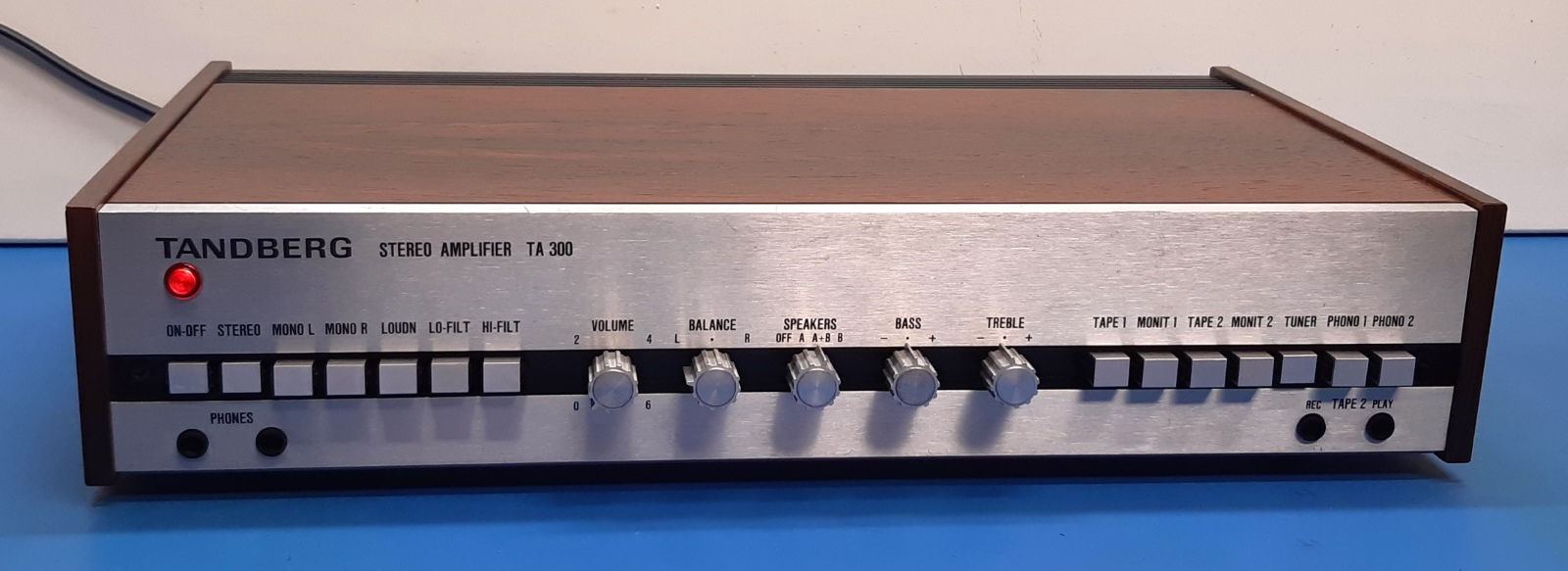
Refurbishing a Tandberg TA300 amplifier, summer 2025
This TA 300 was sold to make some room, and also pay for a too expensive Huldra 10 I was unable to fix because of mechanically defective tuner indication meters I could not source.....
![]() Gemakshalve is deze pagina alleen in het Engels geschreven.
Gemakshalve is deze pagina alleen in het Engels geschreven.
![]() This page was written using English language only.
This page was written using English language only.
My Tandberg TA300, finished August, 2025 .
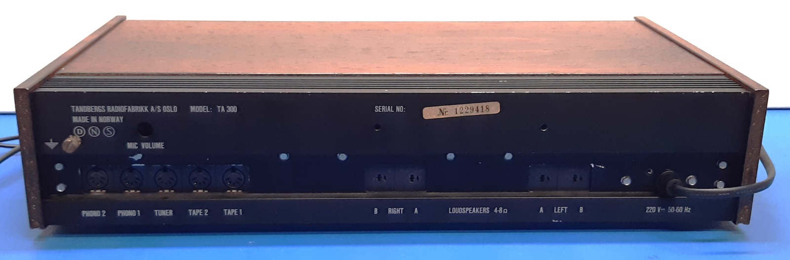
The Tandberg TA-300 is a rather small sized amplifier, having the old style DIN inputs and outputs.
I bought this one as defective, having one channel not working.
The defect itself was one of the big output coupling capacitors feeding the loudspeakers failed "open circuit", after testing using another capacitor it simply worked, although the sound left much to be desired.
The plan was to refurbish it, so the defect did not make any difference for the amount of work to be done.
Still, it is nice knowing beforehand, the restoration will be successful and can hardly be influenced by unexpected surprises.
The idea was to put in new or newer capacitors, metal film resistors instead of the carbon ones, and replace the press-fit old transistors.
All potentiometers and switches needed a checkup for continuity one by one.
This page is written for fellow techs interested in reviving this particular amplifier, it assumes technical knowledge.
![]()
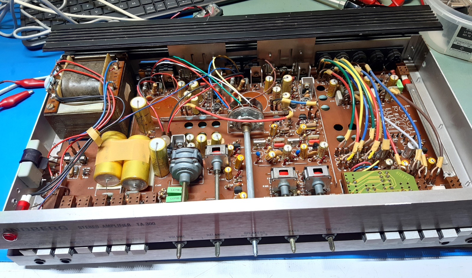
Some observations before taking everything apart:
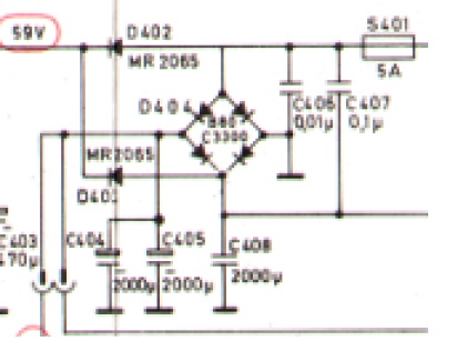
The first thing puzzling me was the power supply, as it was drawn in the schematic. In the end, there are TWO 2200 microfarad capacitors as main power smoothing capacitors, not THREE.
Apart from that, there is a drawing error, the bridge rectifier (drawn as 4 diodes) should be drawn 90 degrees clockwise. Fortunately, it is a drawing error only, otherwise the amplifier would never work...
Furthermore, everything looks pretty straightforward, and not much surprises are to expected.
See the following picture showing the erratic piece of the power supply drawing: (the most right 2000uF capacitor C408 is the one which is not present in the real!)
![]()
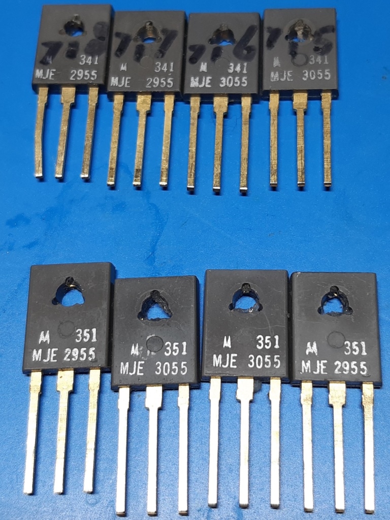
The main amplifier transistors.
The Voltage amplifier transistor used in the main amps has an odd Motorola partnumber, it is an SPS5384. Noteworthy is this is supposed to be the same as a BD529, according the "radiomuseum" site.
The big output transistors are of the original Motorola type MJE2955 and MJE3055.
Fortunately, I had an extra set of output transistors, as one MJE3055 was bad. As Tandberg used a specific way of mounting them, replacements are very expensive, as TO220 substitutes do not fit. Other manufacturers make TO-220 ones only, having the leg too narrow to fit the connector sockets Tandberg used.
One MJE3055 had an extremely low HFE of 5, the other one was barely within specs but at least the HFE graph was tilted upward on my DCA75 tester,
One MJE3055 was used from the other set of transistors I had.
Those came from a butchered Huldra 10, I considered not worth repairing because of defective tuning meters I could not source.
If NOT wanting to modify the mounting, one has to use Motorola ones. This because of the legs width needs to be aligned with the sockets.
Apart from that, the aluminium cover plated presses against the temperature pickup transistor for quiescent current regulation, so thickness is aligned depending on physical thickness of the transistors, too.
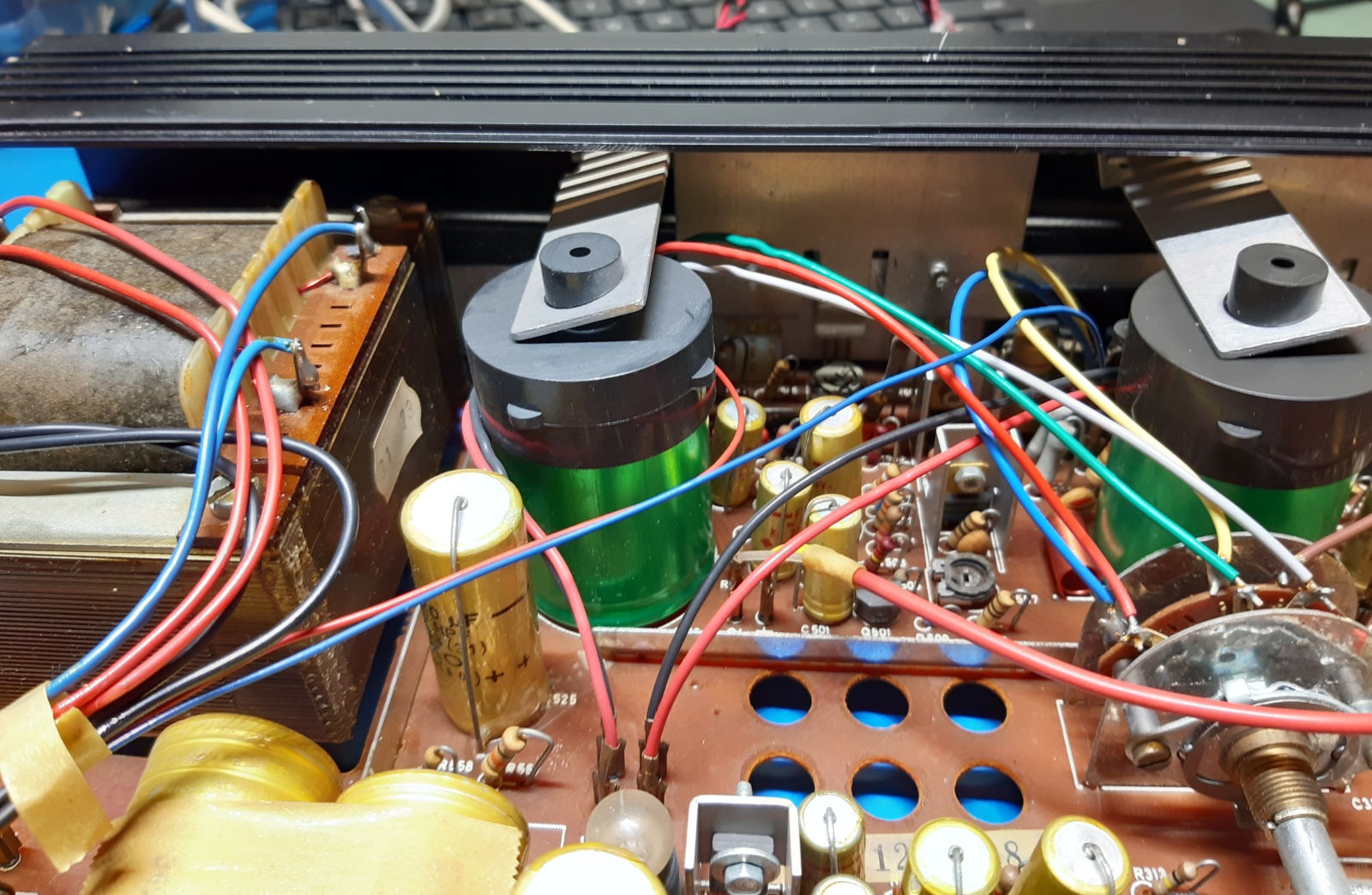
On the picture on the right the aluminium mounting plate can be seen in between the green amplifier output capacitors.
![]()
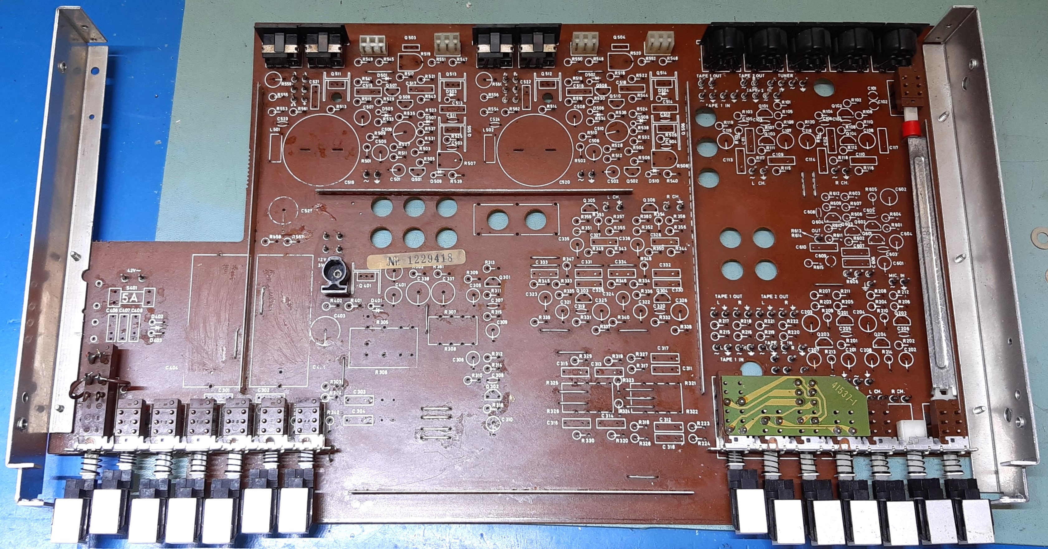
Restuffing the circuit card.
Several electrolytic capacitors were checked, most are detriorating according my Quadtech 1715 LCR bridge meter, except for the Frako ones having a double seal indent.
After removing most parts, the potentiometers were cleaned and checked, they appeared all good.
One of the switches acted up, it did get some extra spray, it was checked working again before soaking the whole pcb in water and soap. A slight amount of Kontakt 61 was used on each potentiometer, the switches were not treated as they are hardly used.
Some electrolytics are replaced by film capacitors. The two big amplifier output capacitors are smaller now, they now have no plastic black cap and metal fixing anymore.
All small signal resistors are replaced by metal film ones, to make sure really everything is done to get noise level down and quality up.
With the exception of bc556 and bc546 in the main power section, all (npn) small signal transistors are of the BC549 type, now.
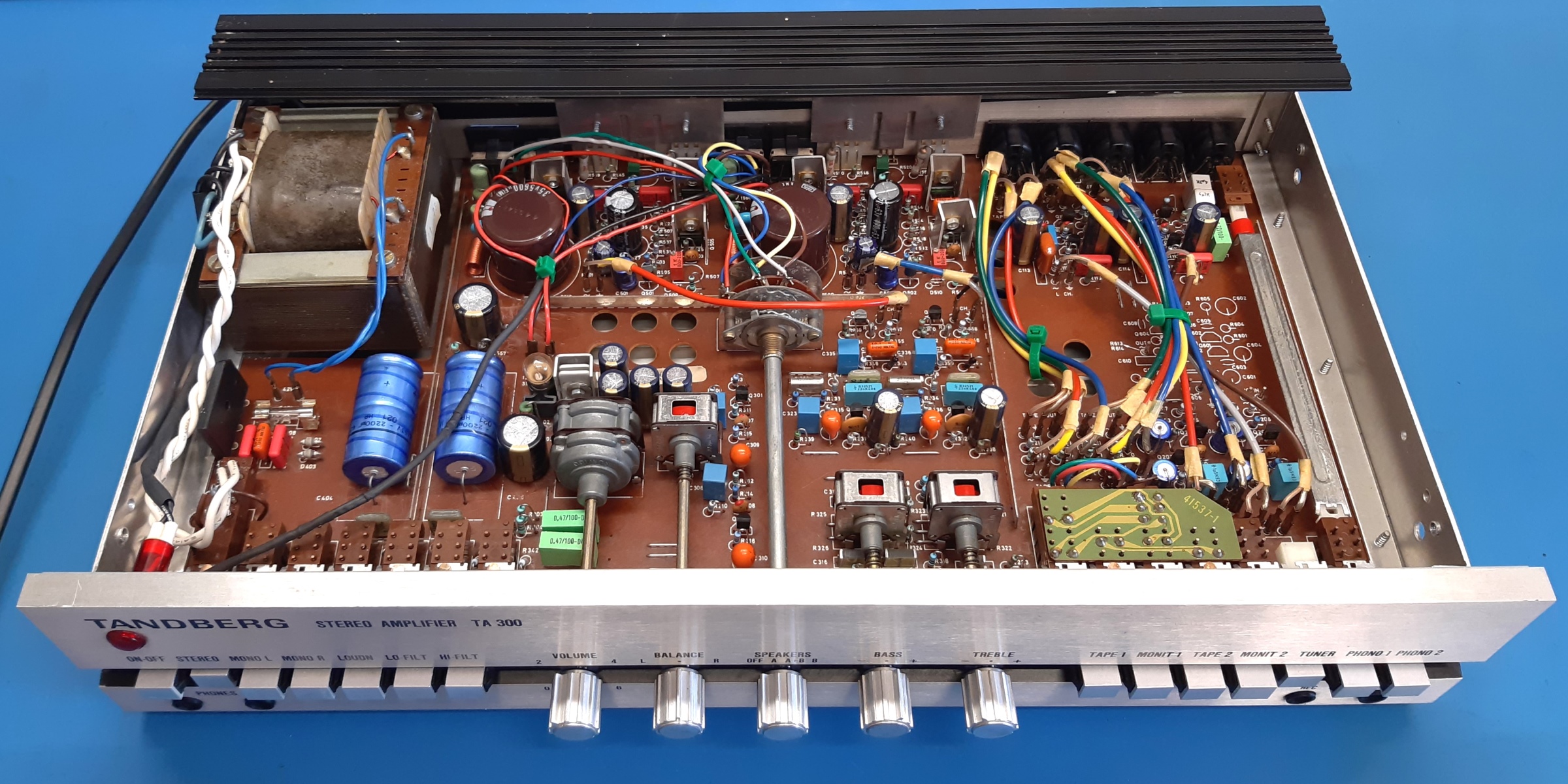
The restuffed amplifier:
![]()
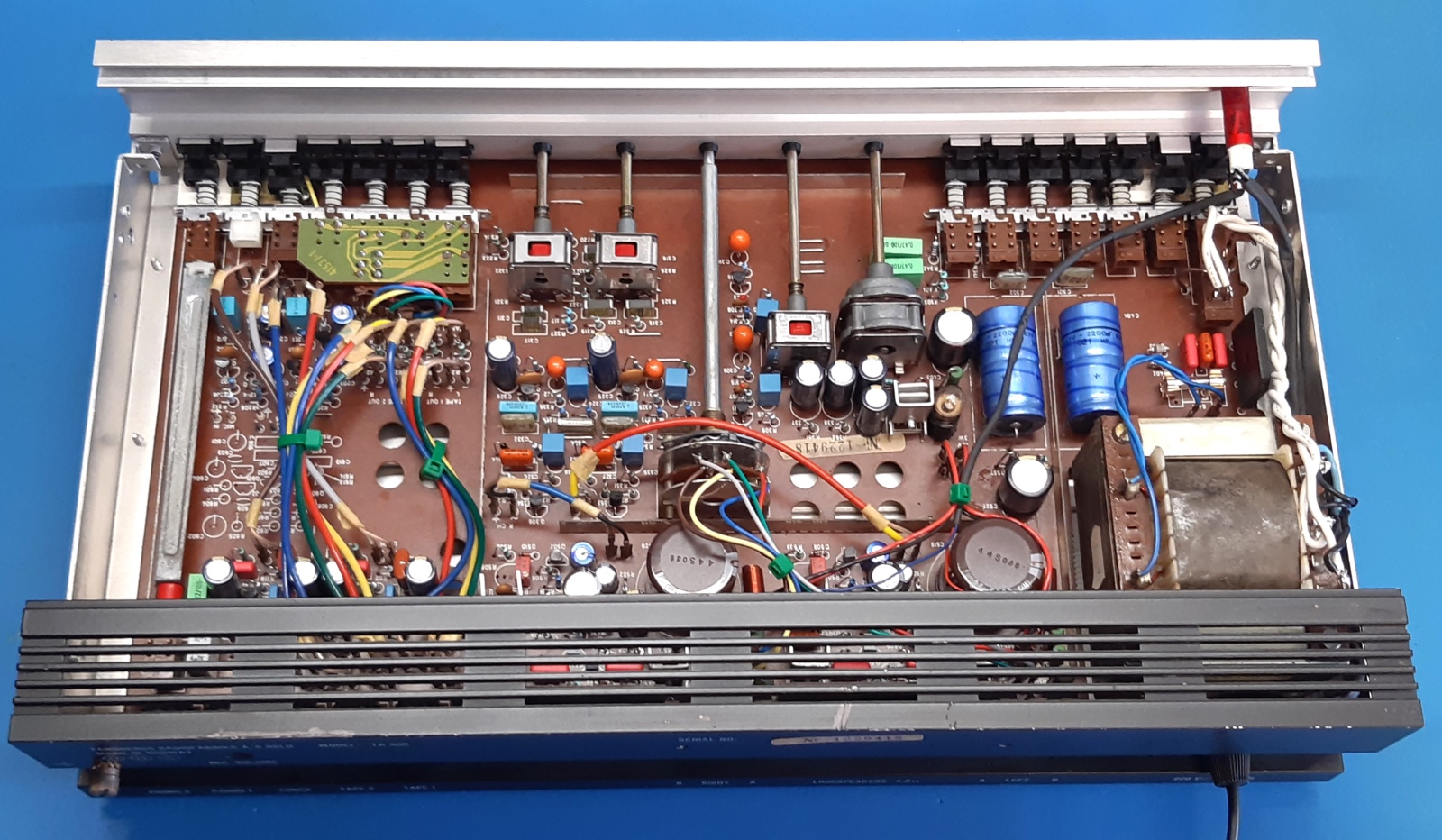
Various pictures of the nice now good sounding amplifier.
![]()
Ga naar Gerards page / go to Gerards other pages ---->>> ![]()