Ga naar Gerards page / go to Gerards other pages ---->>> ![]()

Refurbishing a Sugden A21 MK III
This Sugden A21mkIII is for sale in the Netherlands, fixed price 400 Euros, cash and Local Pickup in Heiloo as I do NOT ship.
![]() Gemakshalve is deze pagina alleen in het Engels geschreven.
Gemakshalve is deze pagina alleen in het Engels geschreven.
![]() This page was written using English language only.
This page was written using English language only.
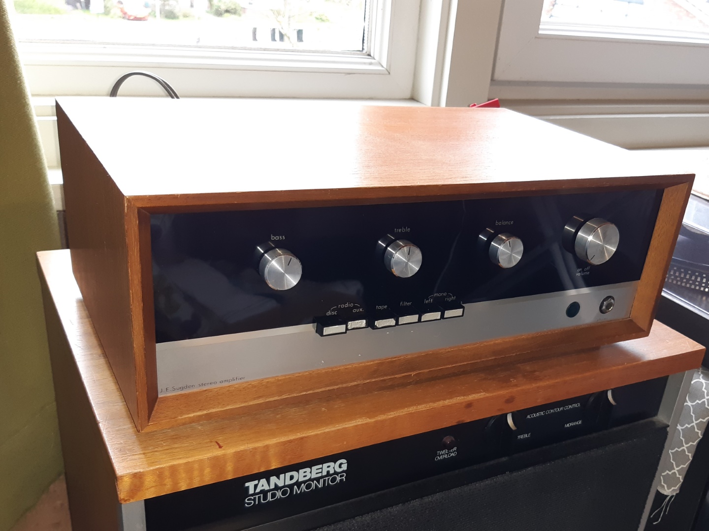
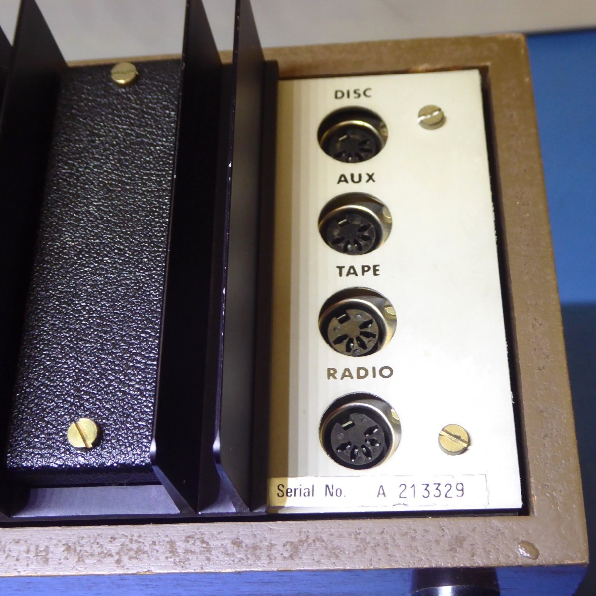
My Sugden A21 MK III, finished April, 2025 .
I was able to put my hands on this very cute British cult amp.
Although it initially sounded very bad and hissing, it still worked more or less, and it looks physically in good shape for its age.
It is very worthwile to preserve this one, as it is "less easy" to refurbish, most of those probably ended up in the garbage, already, working ones will be very scarce.
It did not come cheap paying a lot, but having the opportunity to work on it, makes it worth it.
![]()
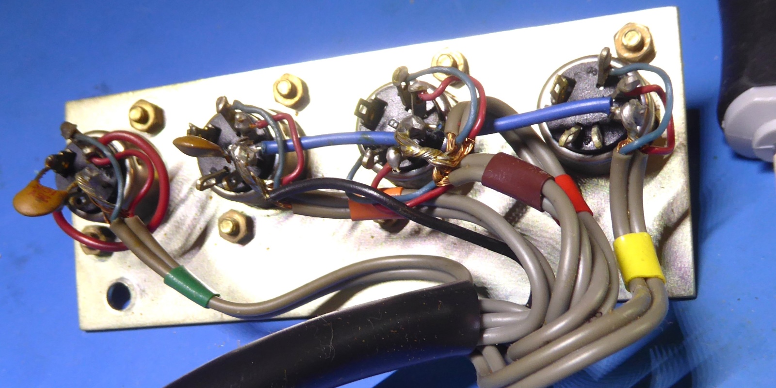
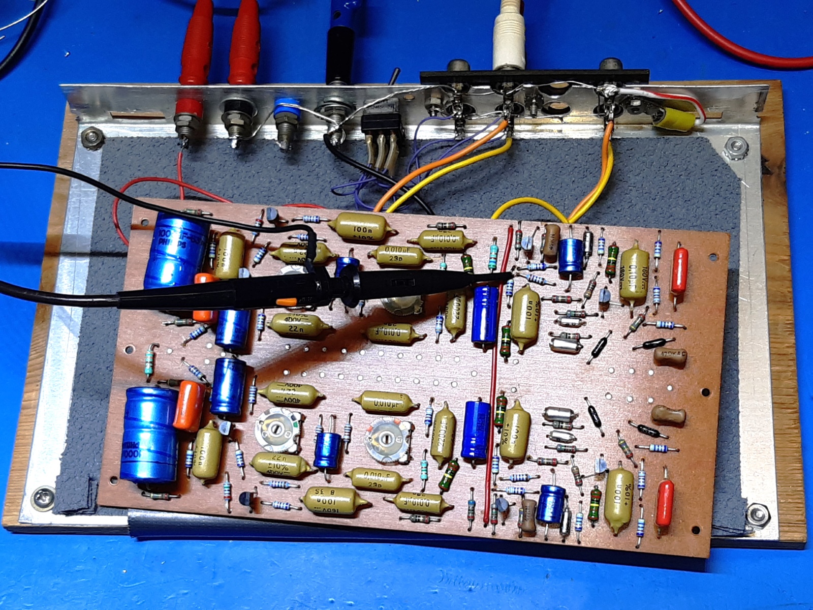
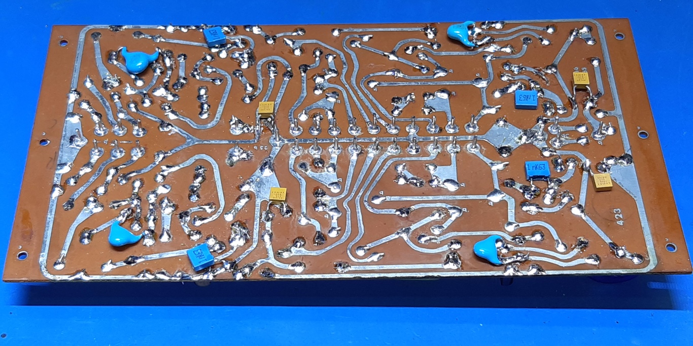
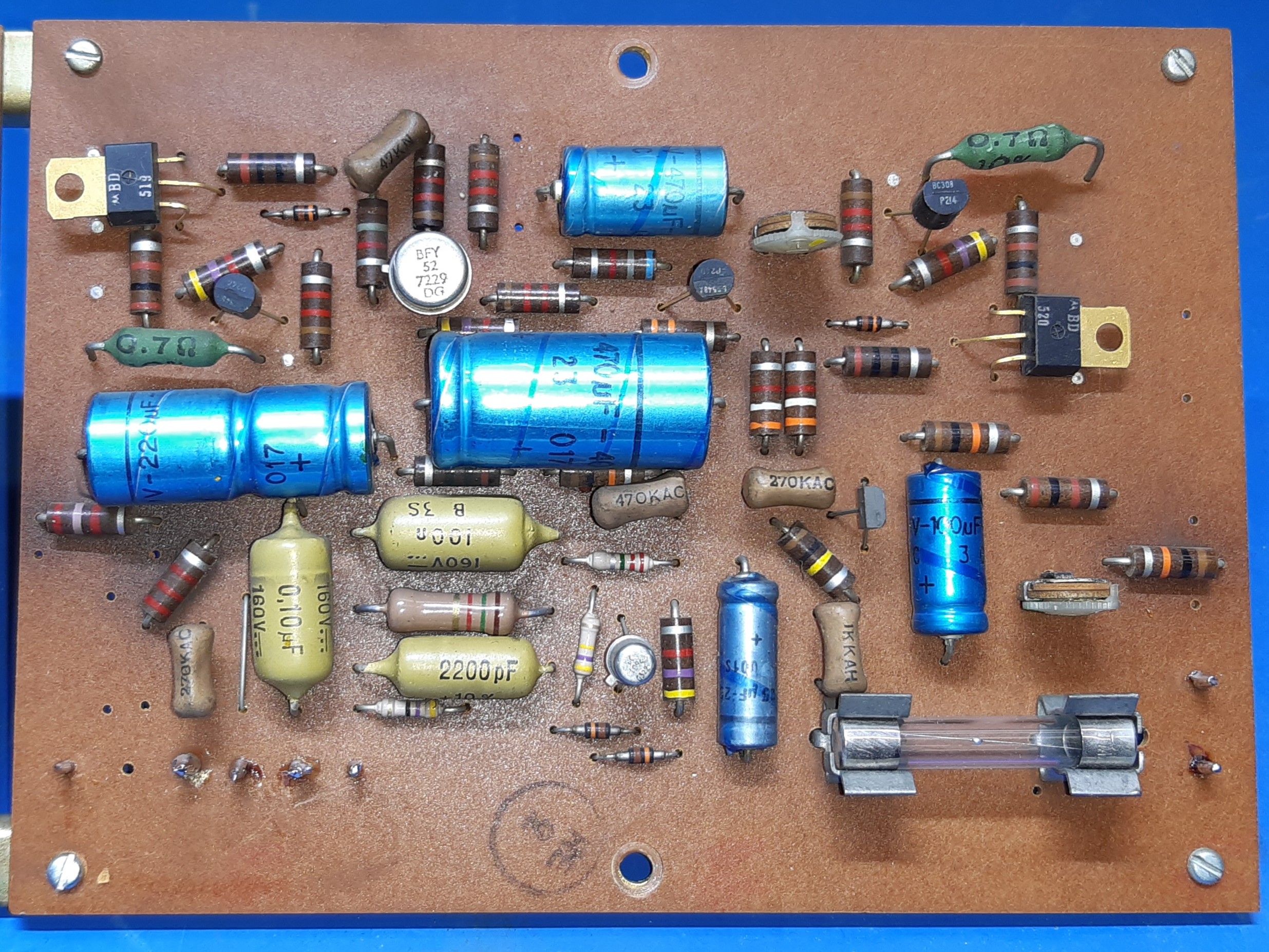
The pre-amplifier
The preamp board is mounted attached to the front of the amplifier, it has wiring to a switch array and potentiometers.
It is shielded by a metal plate and hard to access.
Because of wanting to replace a lot of components, I wanted to take everything off, including the switches and potentiometers, leaving no wires attached to the circuit card The components orientation suggests more or less the amp design to be a DIY effort more or less, but as this is the Mark III one of this amp series already, this is not the case. The majority of components was replaced, leaving no noisy carbon composite resistors, or any other suspect-for-deterioration parts. Transistors are BC549C, now.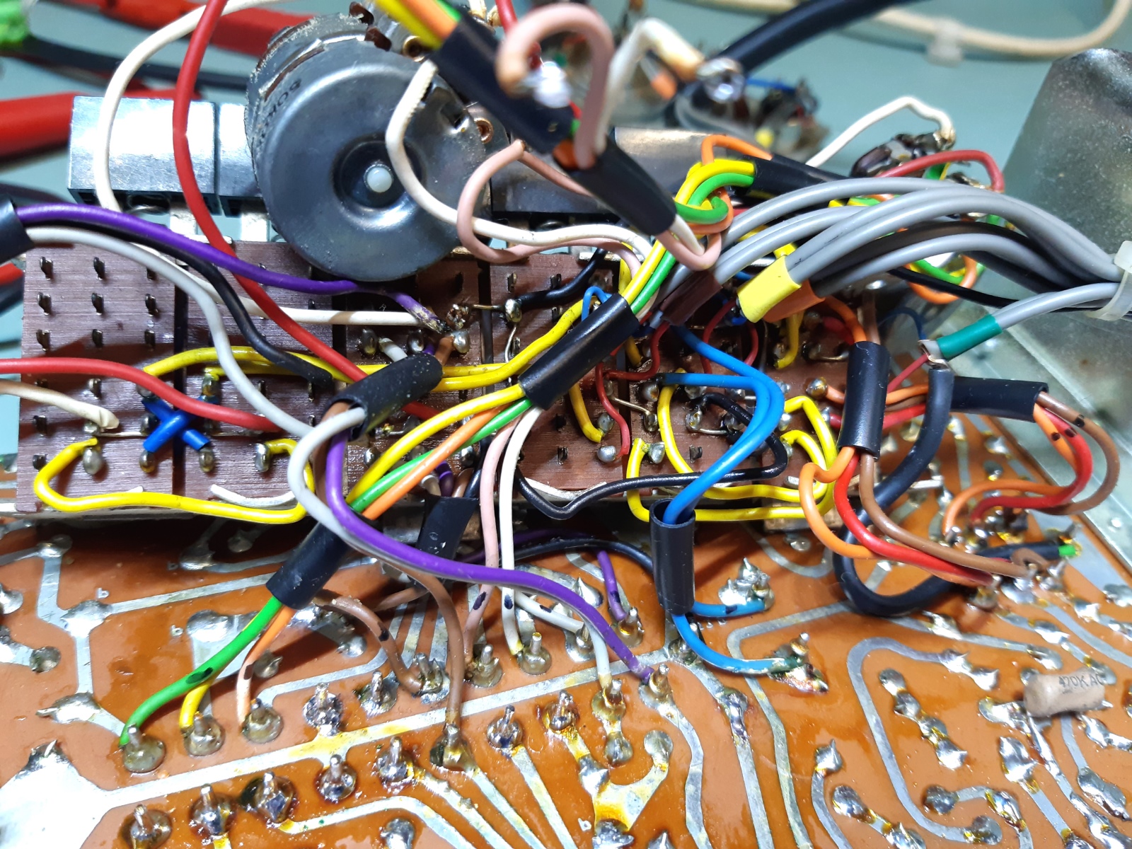
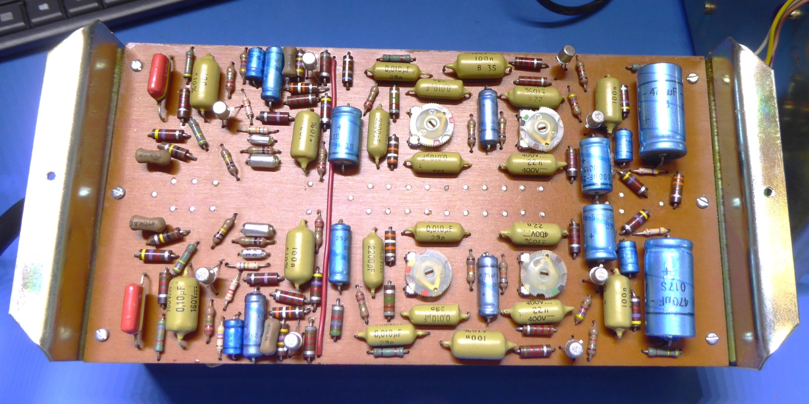
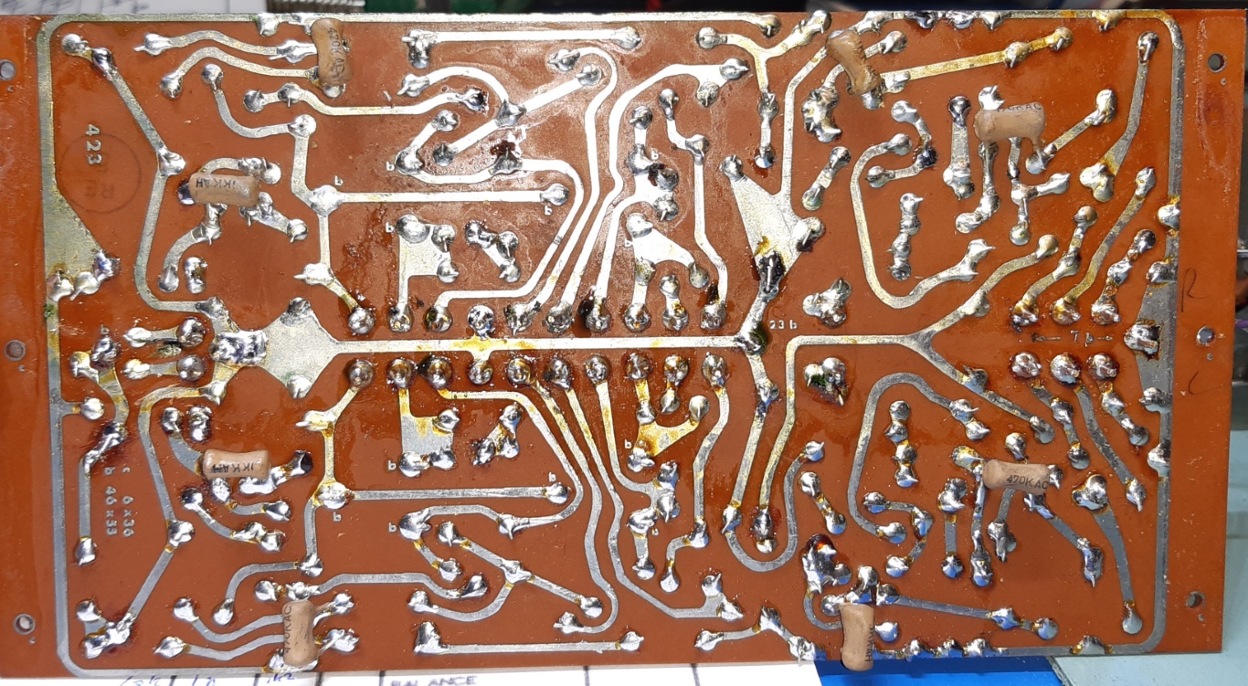
I left most of the "mustard" capacitors on the board, as well as the four trimming potentiometers, after measuring for proper operation.
As the preamplifier is not accessible after mounting it back, the circuits themselves were tested on the bench, assuring nothing was overlooked.
Because the Philips 1000 microfarad capacitors, the two big ones, are older stock, they were tested before for ESR and capacitance. Anyway original was 470 microfarads, they are 1000 now.
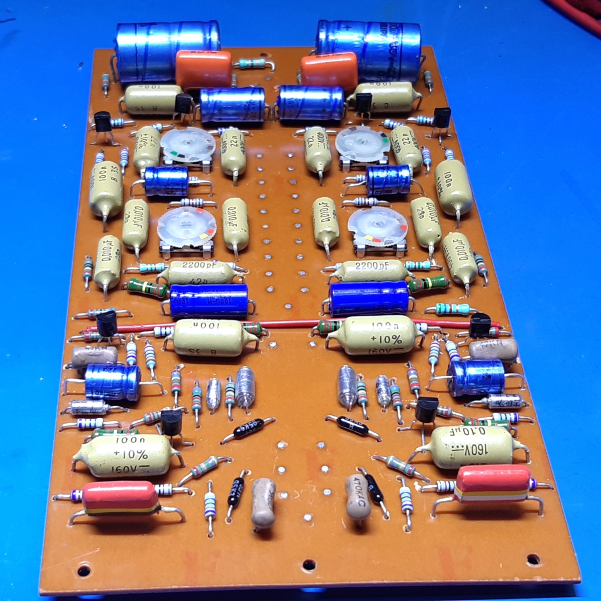
![]()
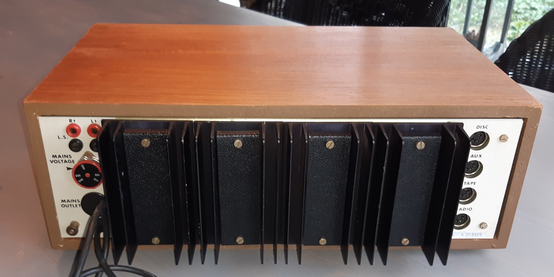
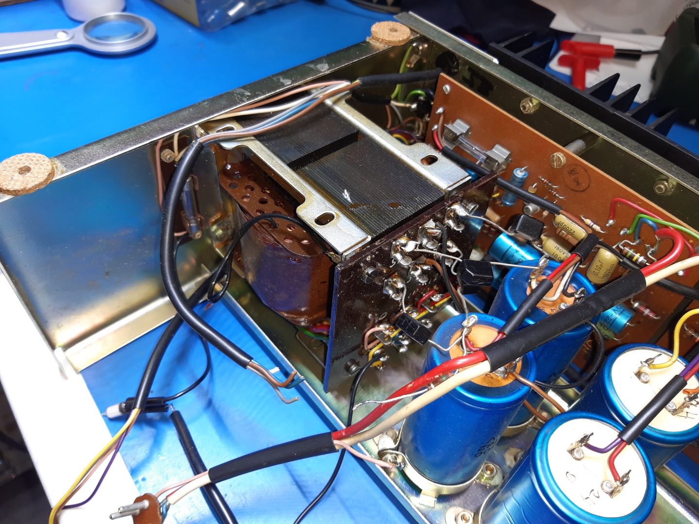
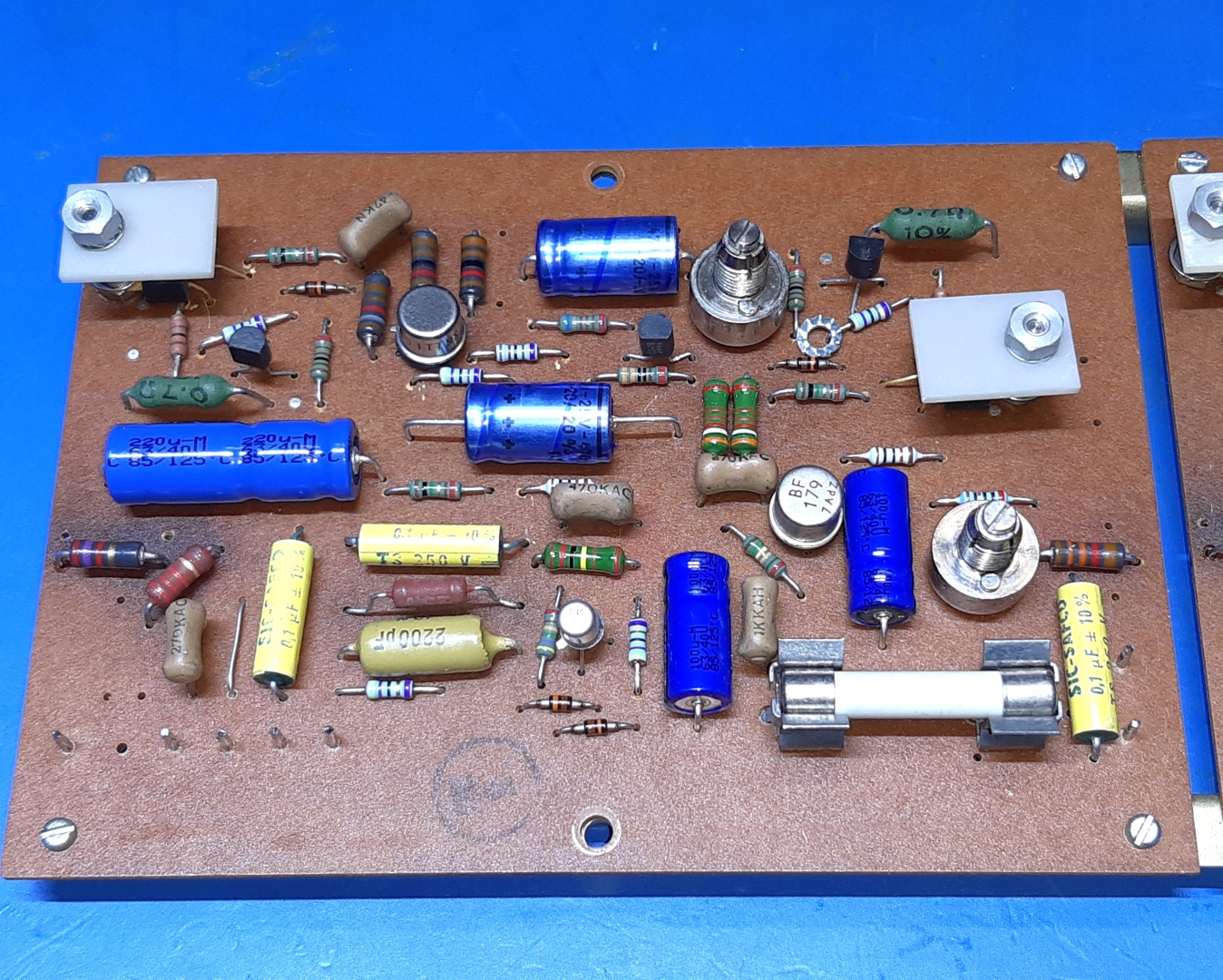
The main amplifier cards.
There next three pictures are of the old main amp situation.
Observe the old rectangular diodes. The big capacitors next to the transformer are for the power supply, the other two are the loudspeaker coupling capacitors.
When moving around, it appears the driver transistors on the board have no heatsink, and they are easy to move, also, so a solution for that was made.
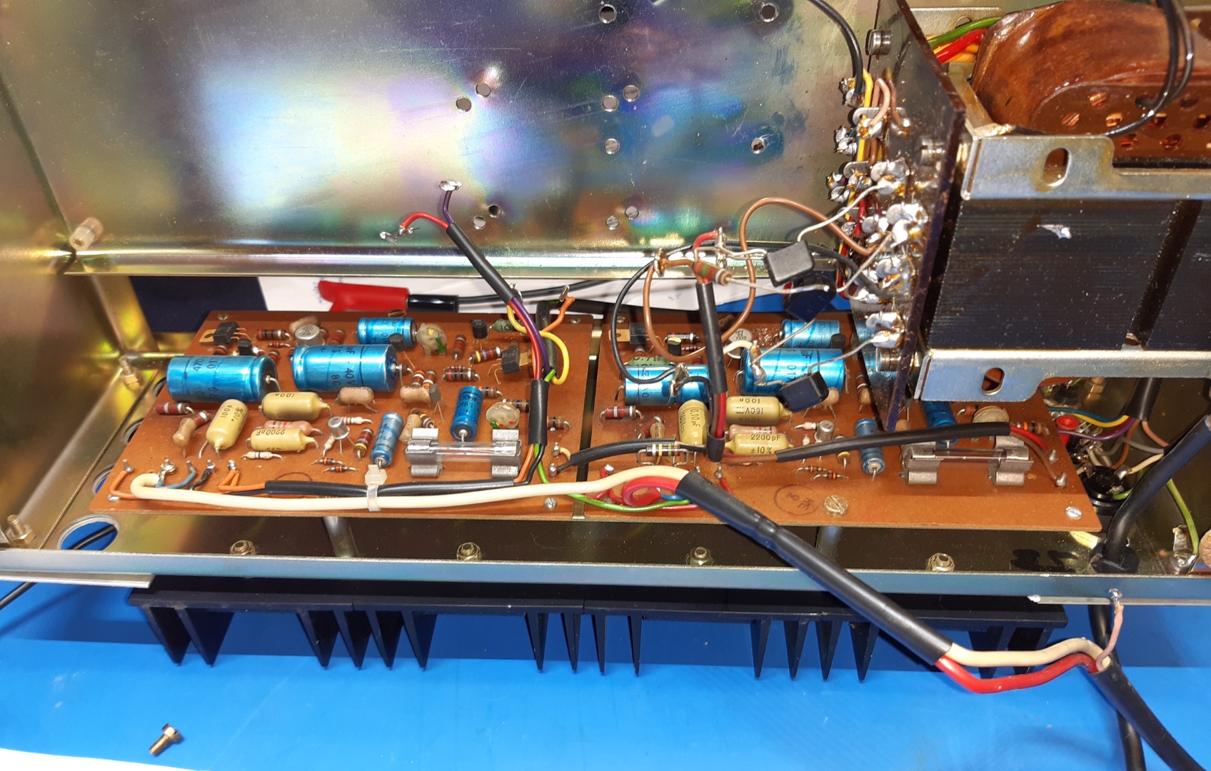
There next three pictures are of the new main amp situation, their output capacitors were exchanged for new ones of the very same type as the power supply capacitors, all being 10000 Microfarads ones
One of the ZTX type transistors was a lot deteriorated, both are BF179 types now, a low-capacitance video output transistor.
I drilled holes to mount both driver transistors, they also have white heat-conductive TO-220 ceramic isolators as a "heat sink".
The BFY52 transistors were still good, and probably they were pre-tested ones (the Sugdens were hand-crafted....), but unsuitable for voltage according the datasheet (40 Volts max! an 20 Volts VCE open base....). I replaced them using 2N3440 ones.
Wanting to use sturdy trimming potentiometers of very good quality I happen to have, made me attache a needle on top of those to have an easy way for adjusting them.
The required bias current of this "MK3" is unknown, I settled for 120 Milliamps, high for class AB but low for class A.
--> Afterwards, having contacted Sugden, I was written the bias is supposed to be 170 milliamps according their technician. They do not have any documentation on the model, anymore.

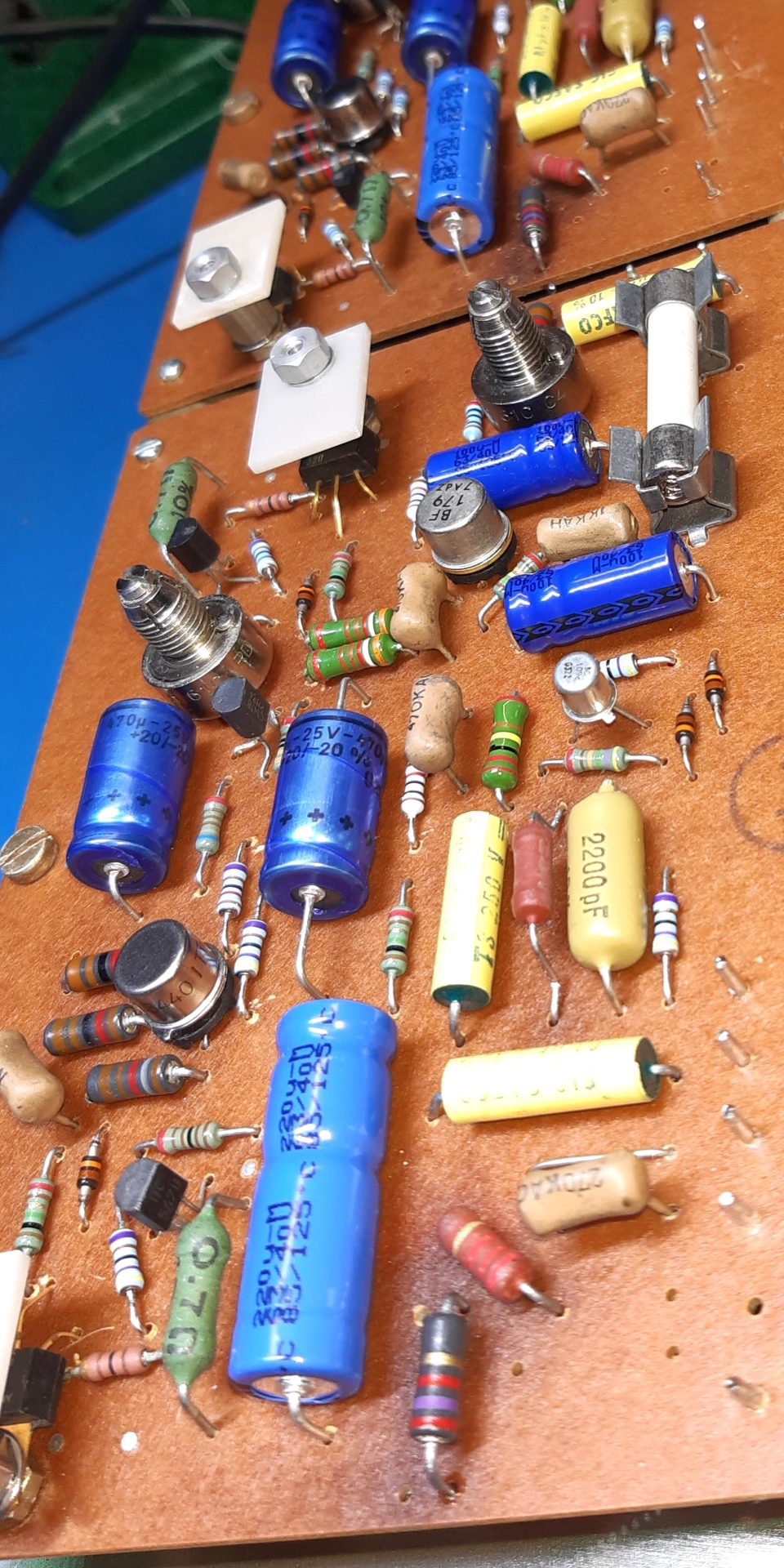
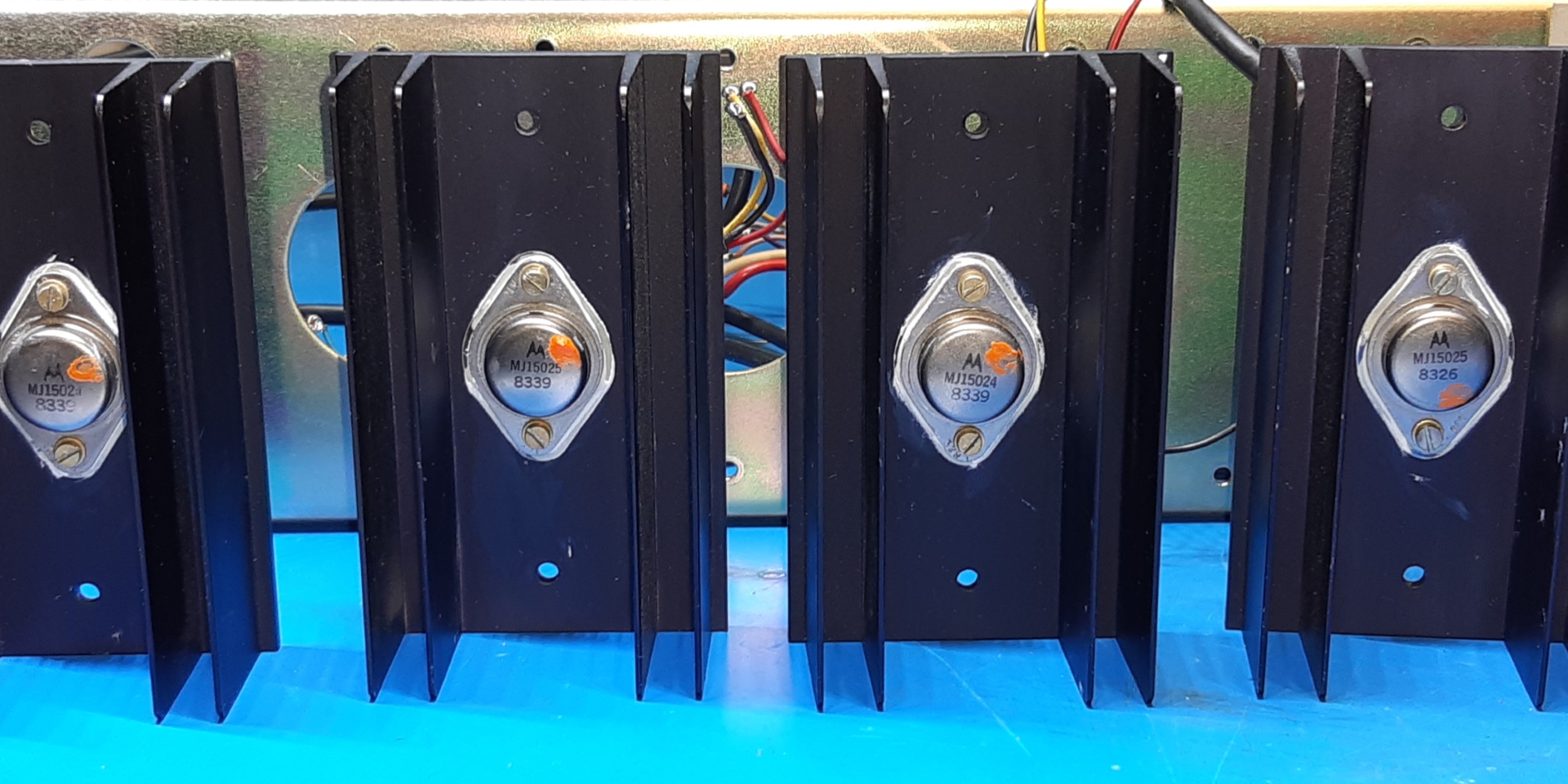
I decided on using MJ15024/MJ15025 to make sure the amp is sturdy enough to work in class A, the old transistors were partly low on HFE so better change them all.
![]()
Various pictures of the now good sounding amplifier.
![]()
Ga naar Gerards page / go to Gerards other pages ---->>> ![]()