
Pioneer SX737 restoration / restauratie, november 2025
This SX737 is for sale in the Netherlands, fixed price 550 Euros, cash and Local Pickup Alkmaar area as I do NOT ship,
Gemakshalve is deze pagina verder in het Engels geschreven.
![]() This page is written using English language only.
This page is written using English language only.
I bought this Pioneer from somebody a few years ago, he decided to try refurbish audio electronics without having sufficient knowledge.
The story was he tried a less risky thing as a starter first, which was updating the turntable input amp using modern transistors.
At the very moment things started going down hill, he and the other guy decided maybe the challenge was too much for them, as they could not get the TT input back in working condition.
In time they decided to call it a day, as now the receiver was still working and usable and most people do not have a turntable anymore.
For them a wise decision, for me a chance to buy this still very nice looking receiver for a reasonable price on driving distance, from a honest seller.
Hooking up the receiver at home, the situation was as described, during the beginning of november 2025 I started the rebuild.
Apart from the leisure pictures of the innards of this receiver, audio electronics knowledge and ability to grab your documentation from the internet is needed to follow my text, as it is intended as a guideline for others working on a SX737, and some kind of "log"for myself.

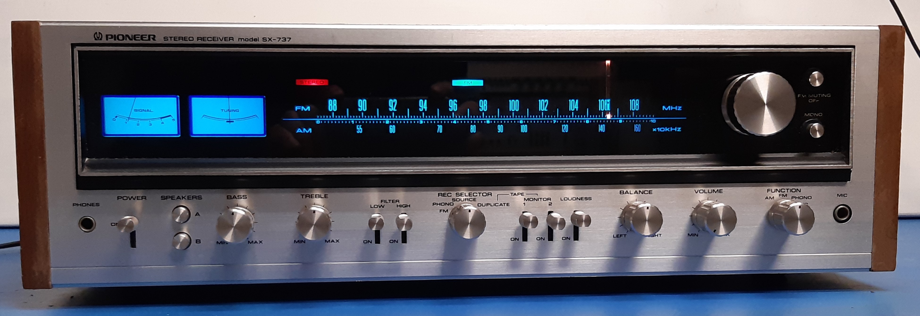
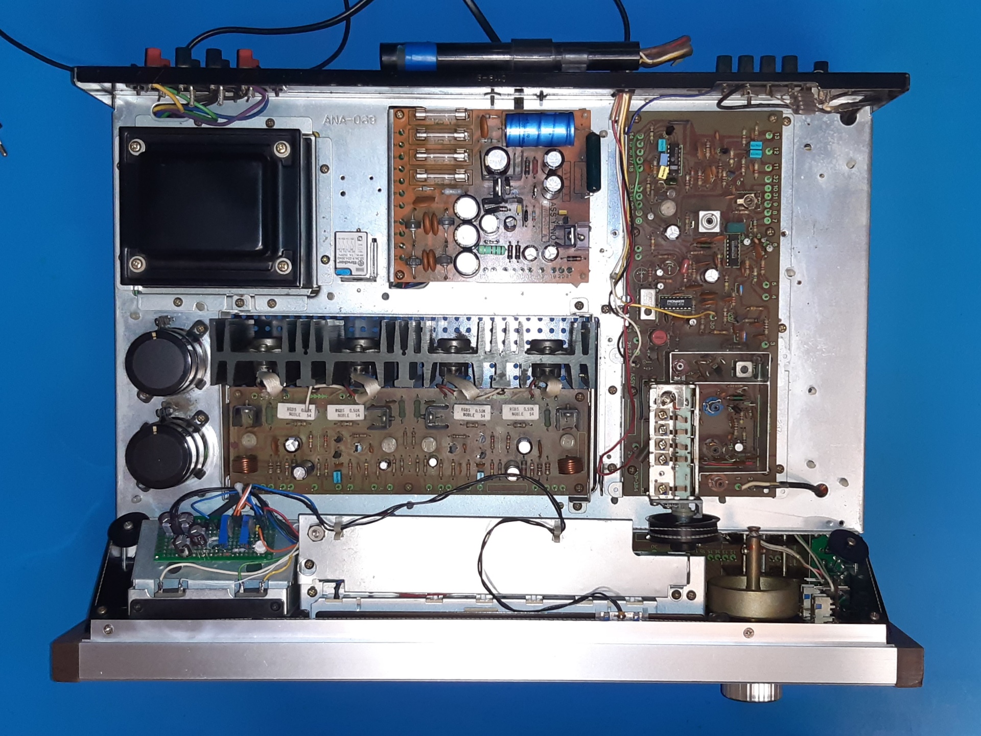
An overview of the receiver as it came, including optical evaluation.
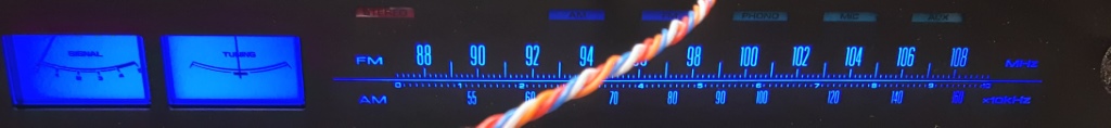
Powering up, it was obvious the scale and meter lamps are rather dim. Optically, the receiver looks in very good shape, considering its age. I tuned a station and music appeared.
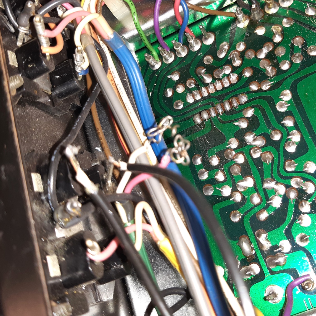
Opening it up, looking for odd things, it was obvious some wiring was compromised.
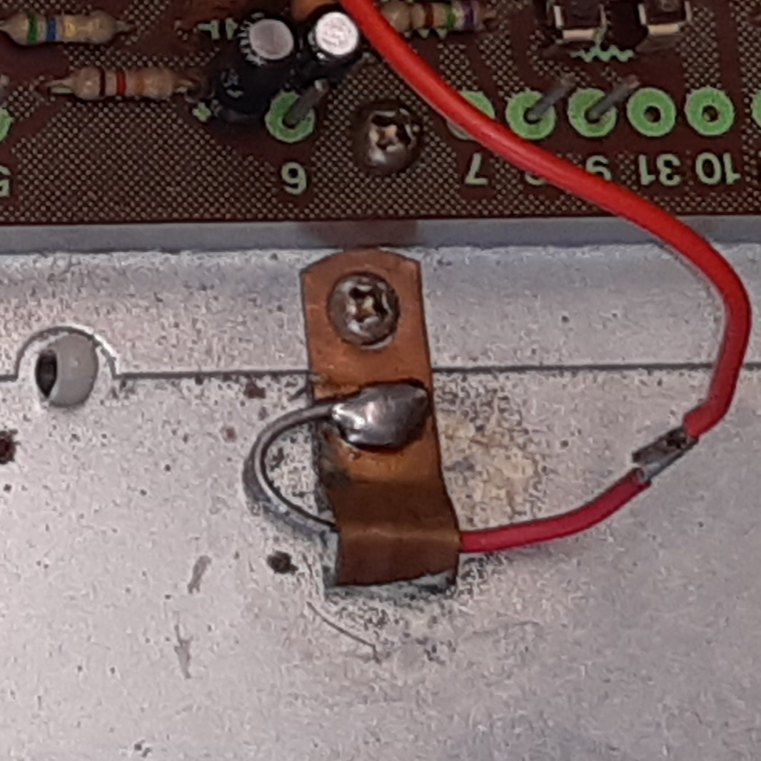
Very obvious is some red wire going from the power supply board to "something" mounted/soldered next to the tuner. (later on it appeared the 14V stabilization Zener diode, clamped to the chassis by somebody)
Apart from that, a jumpered fuse is visible on the power supply card. This fuse belongs to the lamp circuit, apparently it blew during some lamp replacement.
This indicates modifications were done before the previous owner did get this receiver.
Wires at the tape output going to the receiver front were found unwrapped and apparently new black wires are installed.
It looks all those wiring issues go together with soldering problems also.
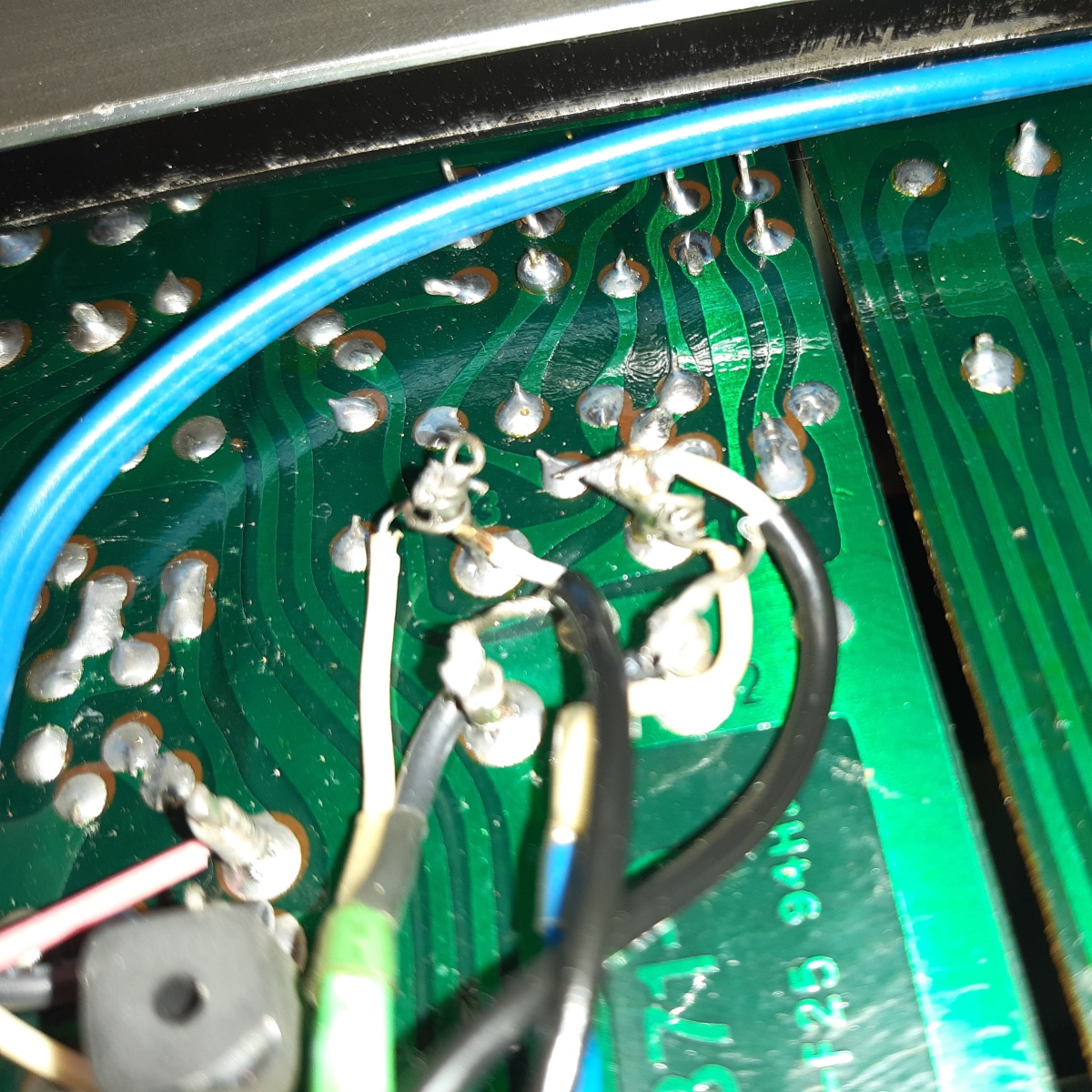
The wiring at the equalizer amp was unwrapped and soldered, the solder looks compromised and the green wire was loose. A capacitor has collateral damage caused by a soldering iron.
Apparently, two wires extra ever were fixed at the protection relay, as there small remains of red and yellow wires visible.
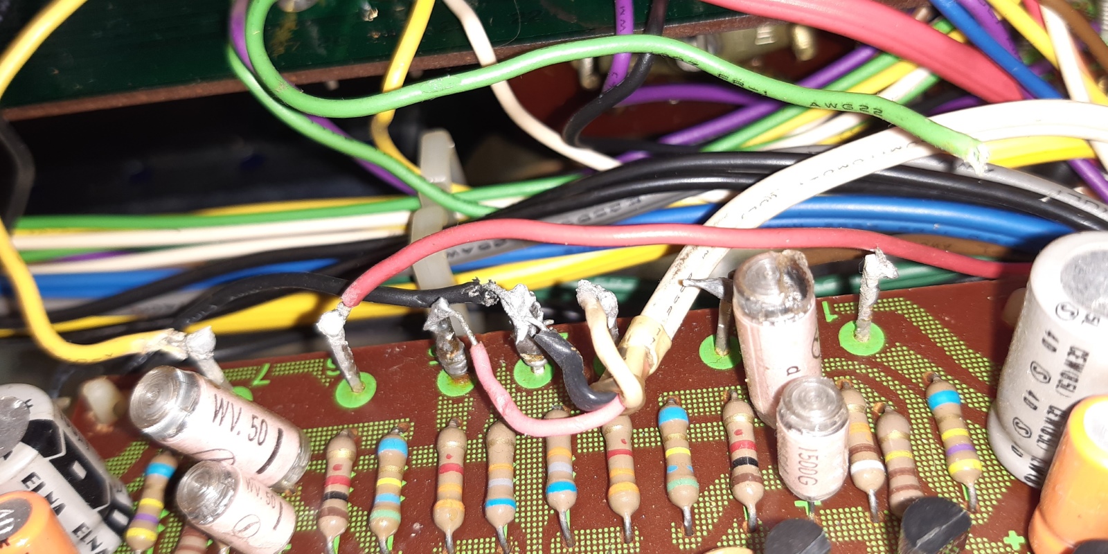
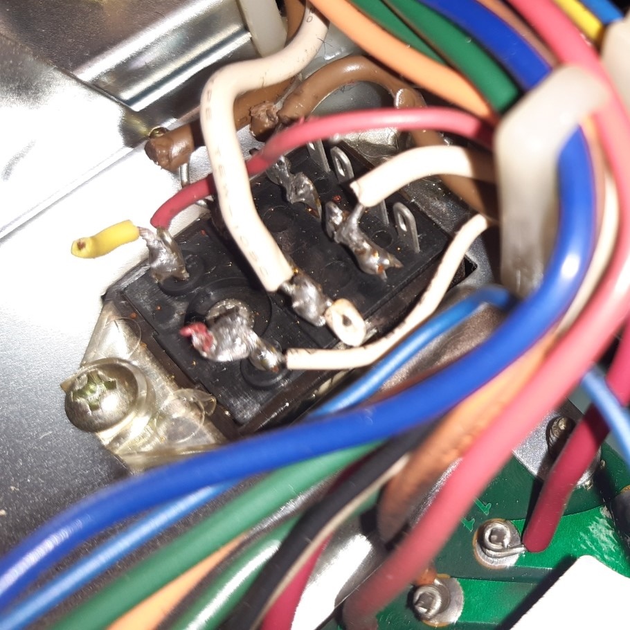
In the end, it looks quite obvious a very bad quality solder was used to try make the new connections.
The last flaw to metion is the fact that although stereo reception was still more or less possible, the signal level seemed lacking a lot on the meter and also the midscale indication was way off.
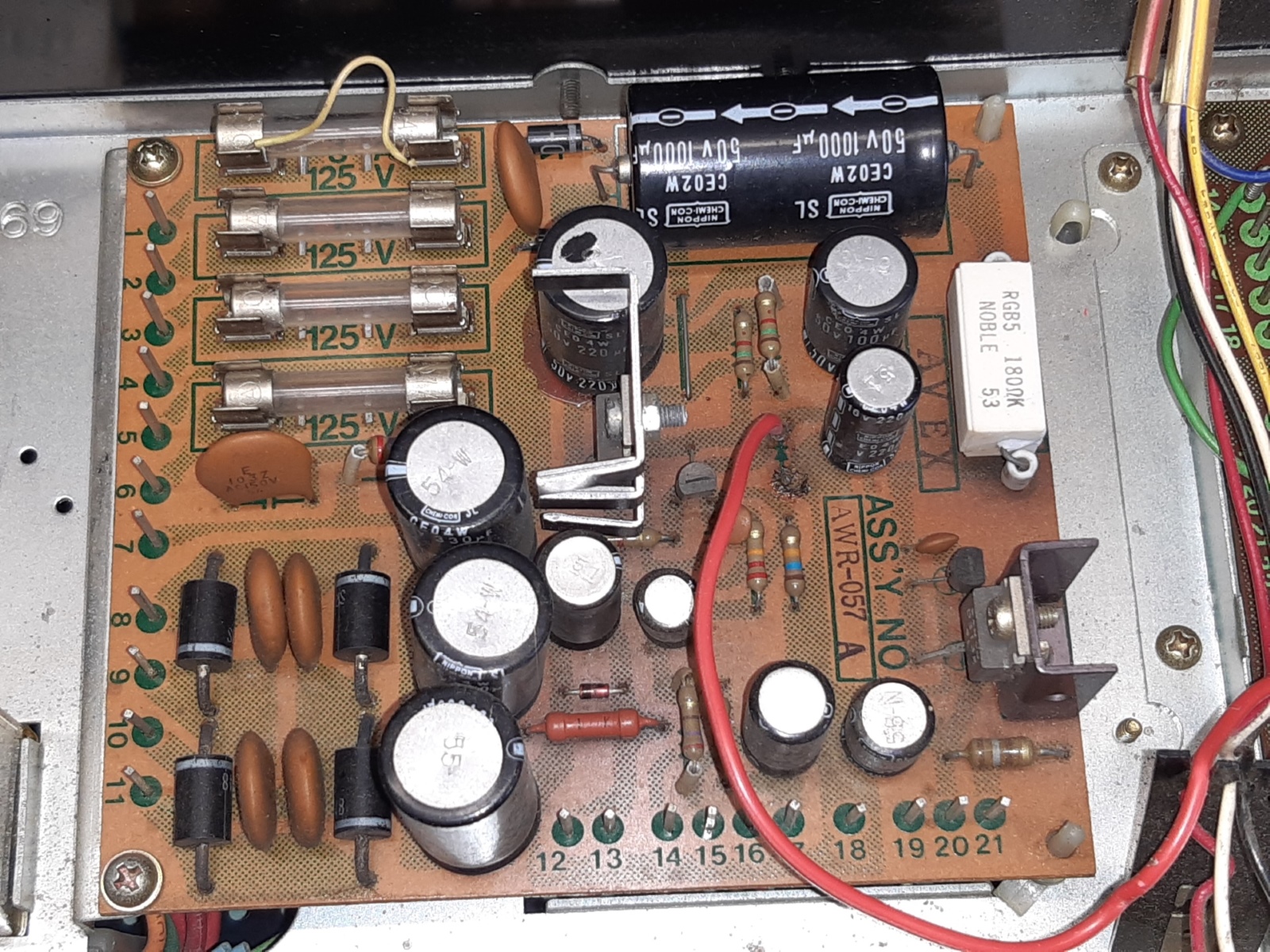
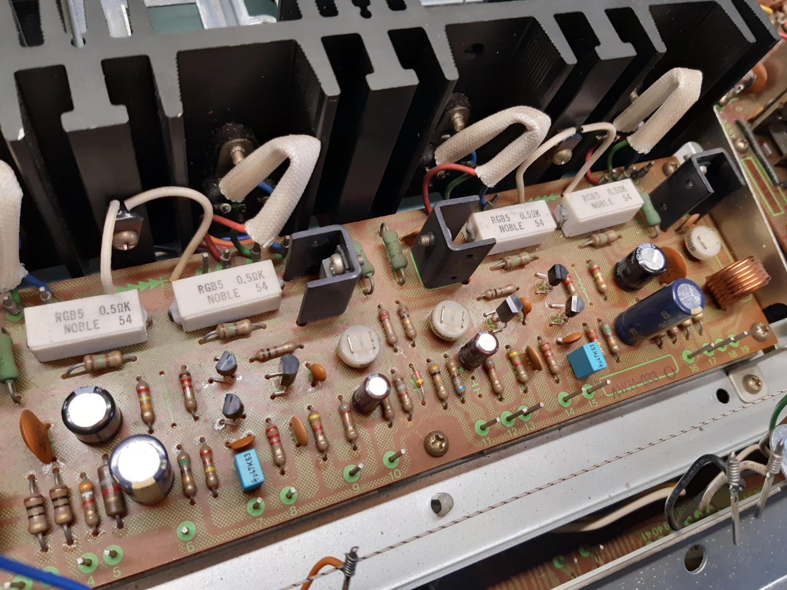
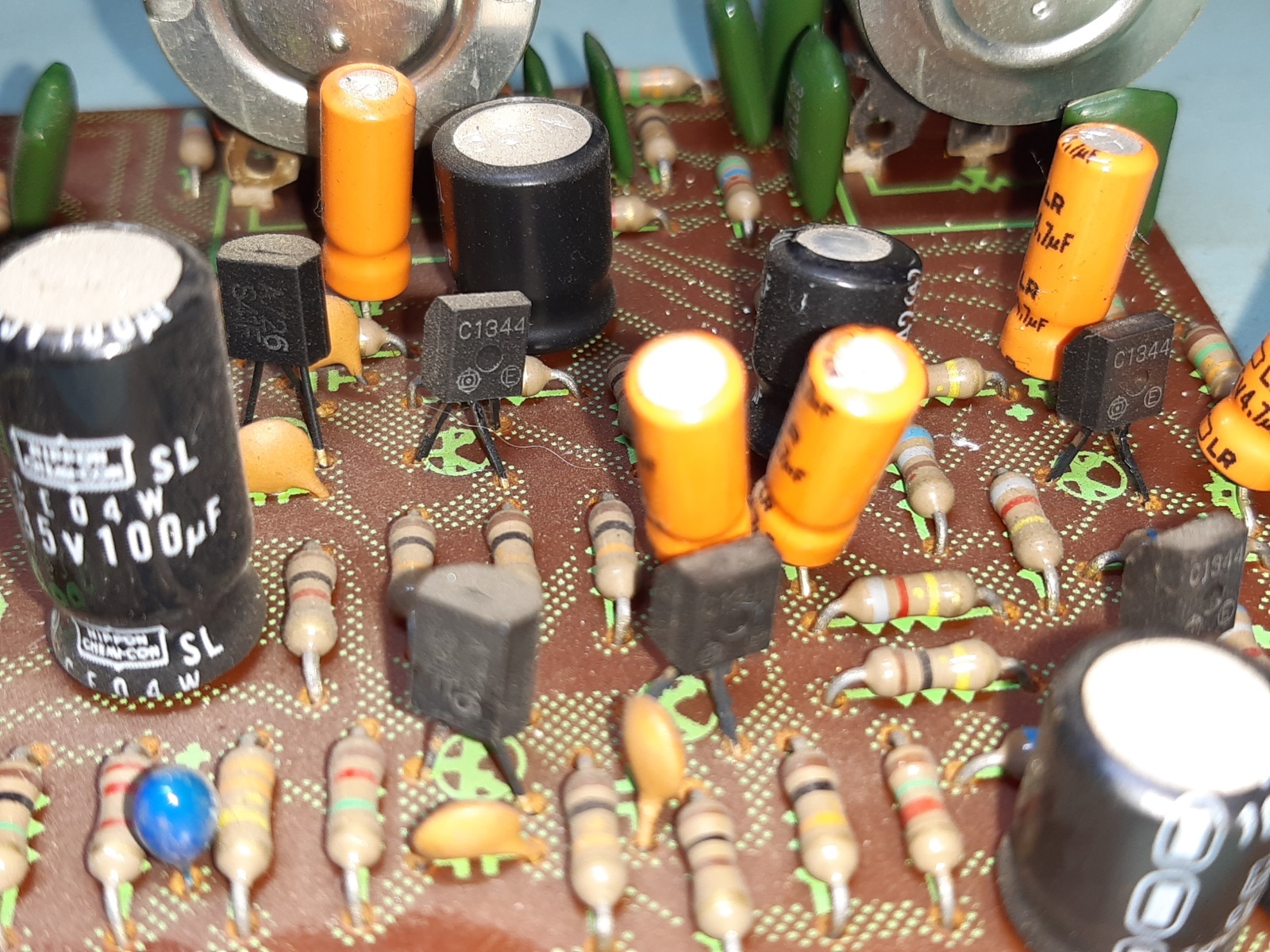
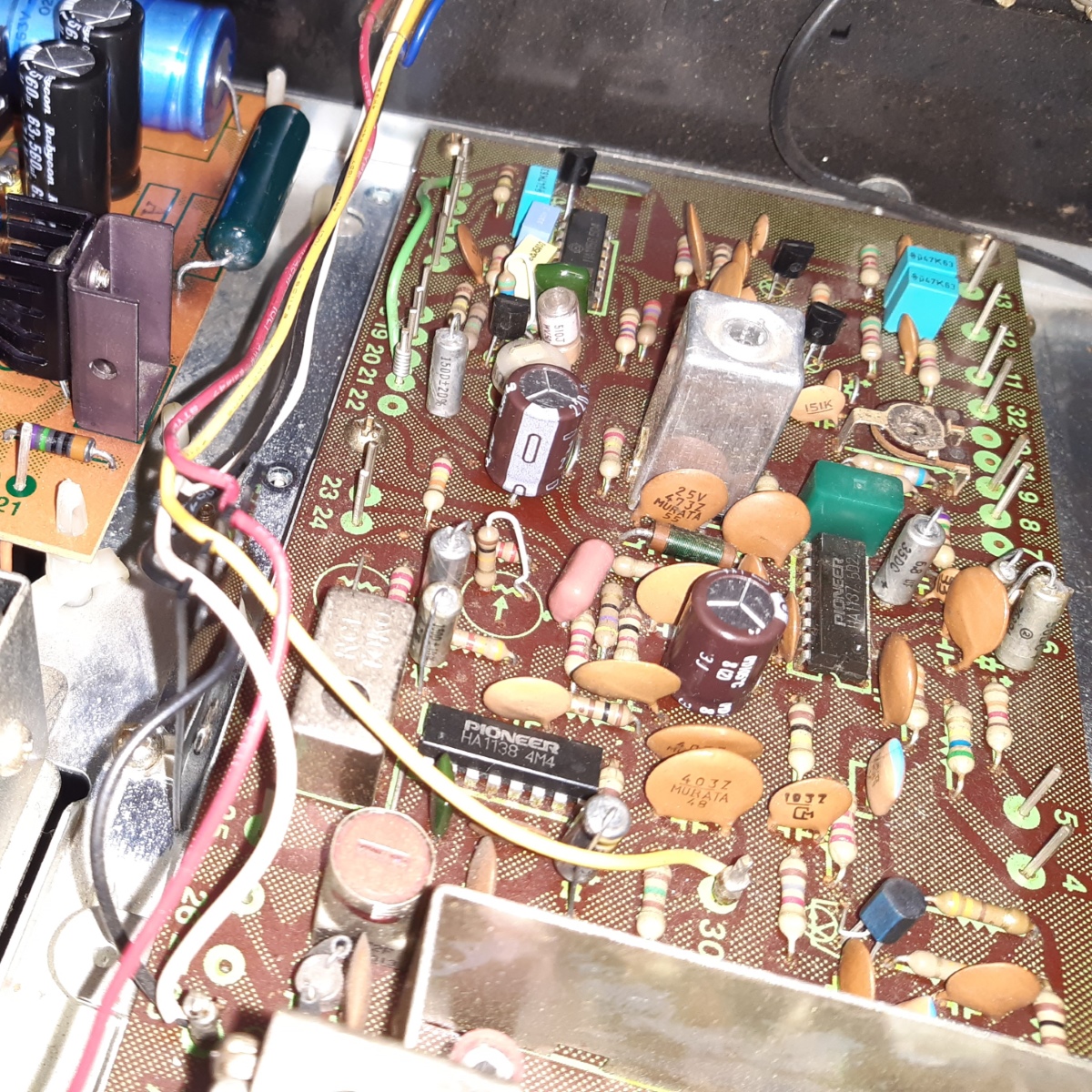
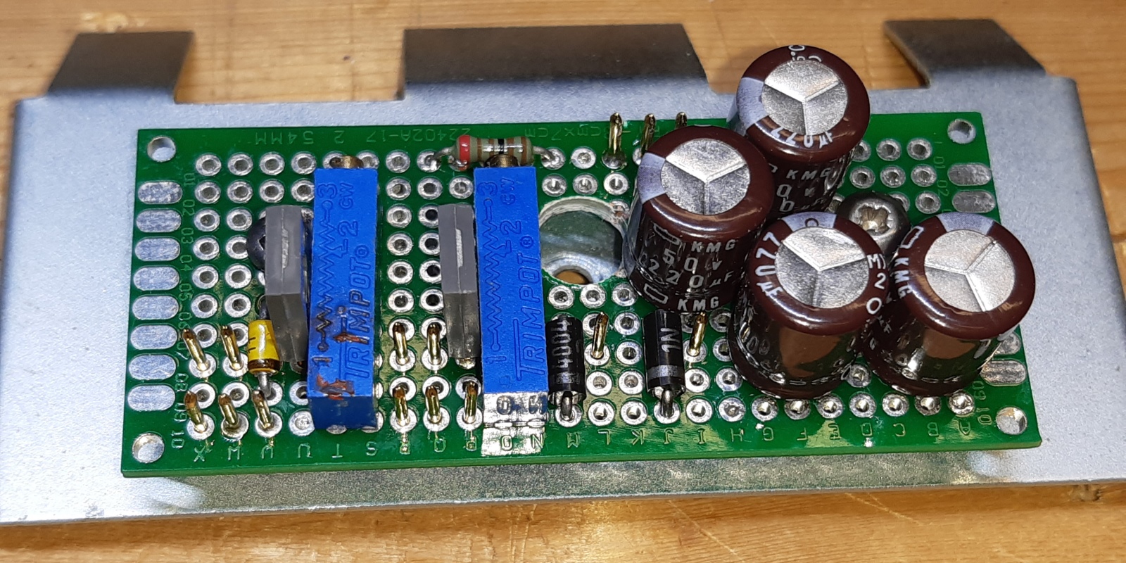
The pioneer sx737 power supply card, AWR057A
Fortunately, on the SX-737 model, the power supply is not mounted upside down frying the whole card over time, alike in the Pioneer SX-838. Still, it gets rather hot.
Removing almost all components, it is obvious where the hot spots resided, so I attempted to migitate the heat a bit when reassembling.
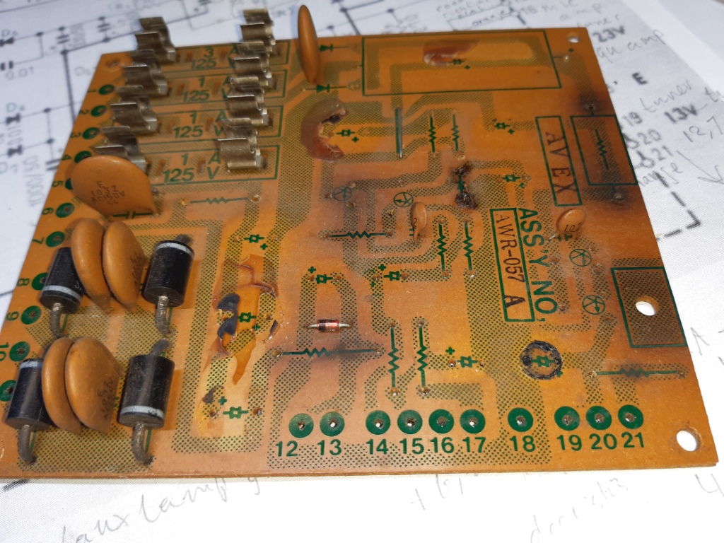
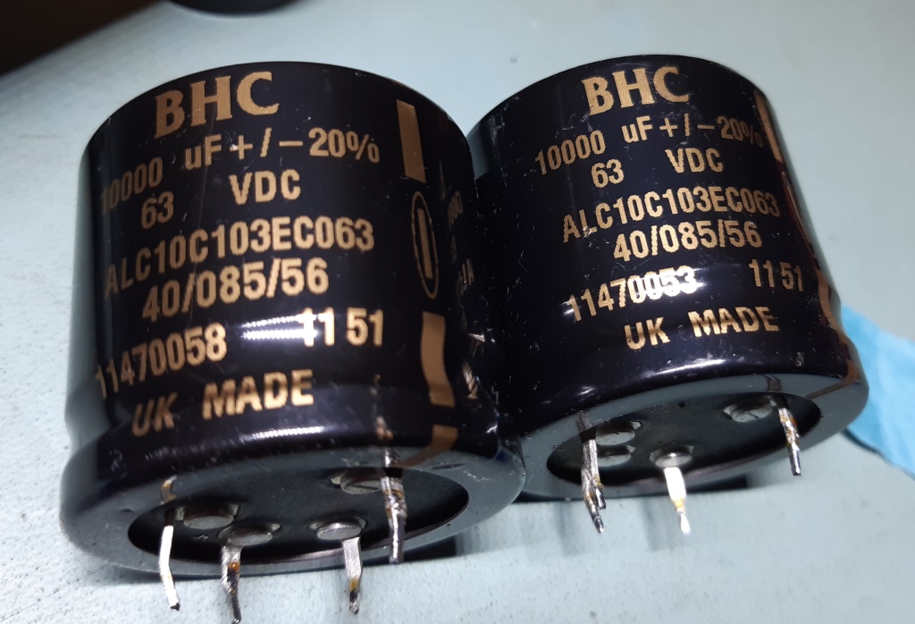
I used new 10000 Microfarad ALC10 smoothing capacitors instead of the originals being 6800, see the picture of them on the right. As I had more sturdy diodes available, I replaced those also, on the power supply card.
The 1N5350 13V Zener diode mounted on the chassis was removed and replaced by two Zener diodes in series, together making the 14 Volts needed according the schematic, the heat is shared over two diodes.
I used higher capacitance electrolytics in general, to make ripple levels lower than it ever was when the receiver was new. Using 560 Microfarad instead of 220 bypassing the Zener diode used the preamp voltage reference as well used as a direct 13V reference for the tuner further migitates low frequency noise zeners are known for. The 2SD313 power transistors were replaced by TIP31A, Q3 feeding the tuner appeared defective after desoldering, so apparently it was already vulnerable. Other parts were updated also, the Q3 heatsink now has an extra metal heatsink part added as well as a washer below it, cater for less heatup of the pcb. The total size of the heatsink of Q1 is lower profile now but a bigger size. It should be noted, already a heatsink was mounted at Q1, and Pioneer supplied it without! This was a rather stupid thermal design error as the amount of heat dissipated calls for one. The bigger resistor I used to replace the white cement one, is angled a little offboard on purpose, it will drag air from below going more upwards instead of partially heating up the circuit card. A modification is the small resistor on the most right on the picture going from pin 20 to 21, is was a 180 Ohms resistor, now it is a 750 Ohms one. It feeds and limits the stereo indicator, which is using a LED now, instead of an incandescent lamp. In the end, it is a better power supply than when it was new, and running cooler at the same time.
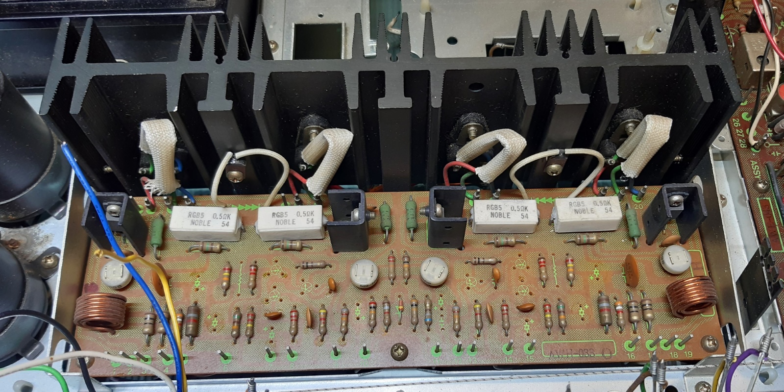
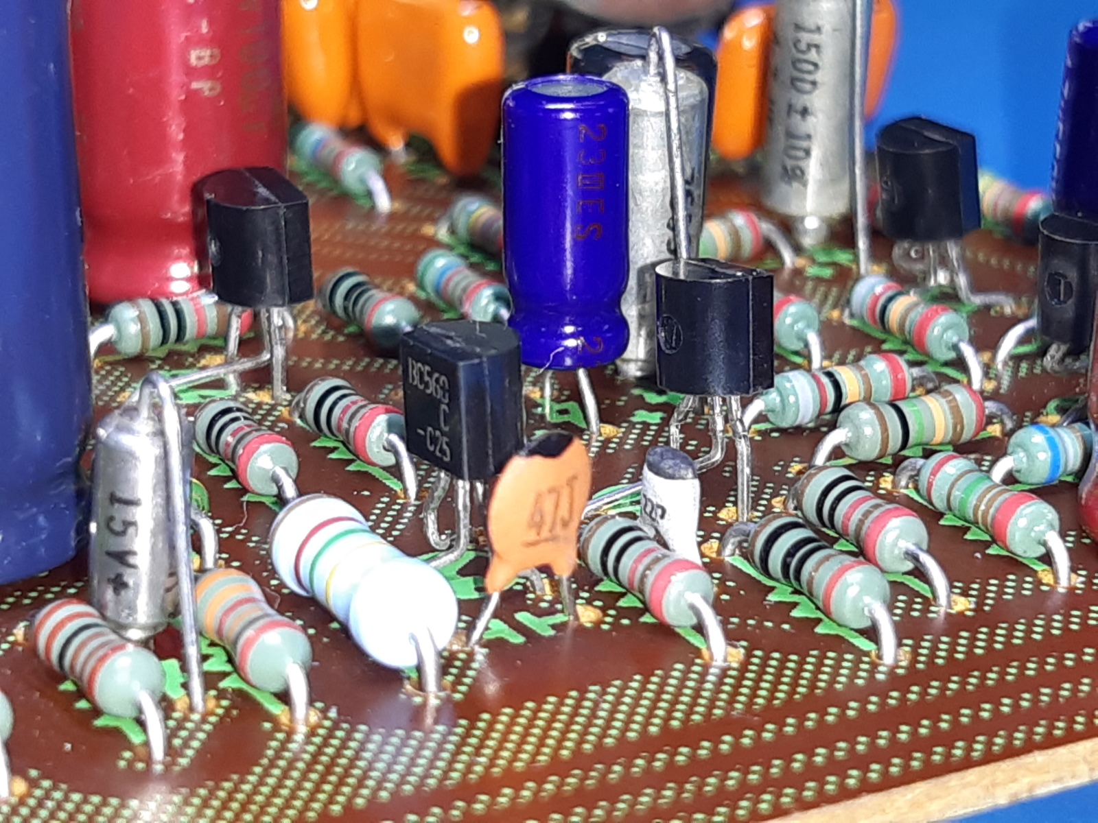
The power amplifier board AWH033-O As I checked the power amlifiers during first power up and they behaved good and look unmolested, I decided to leave just in the card and do a total recap of it, leaving the output section (more or less) alone. The negative feedback DC decoupling capacitors C7 and C8 I gave a special treatment, since when in the amplifier they never see a voltage level to keep them formed again. Therefore I "reformed" them up to their working voltage before putting them in, to minimize deterioration because of the time between production and starting to use them.(shelf life...) Apart from replacing capacitors, I replaced the input pairs of transistors by Diotec BC556C matched pairs. The always "suspect for deterioration" 2SC1451 transistor used for the voltage amp stage I replaced by a KSC2330. This transistor has very alike specifications and behavior also measured almost the same for DC, compared to the old 2SC1451 ones coming out. The picture on the left shows all empty spaces where new components now reside.
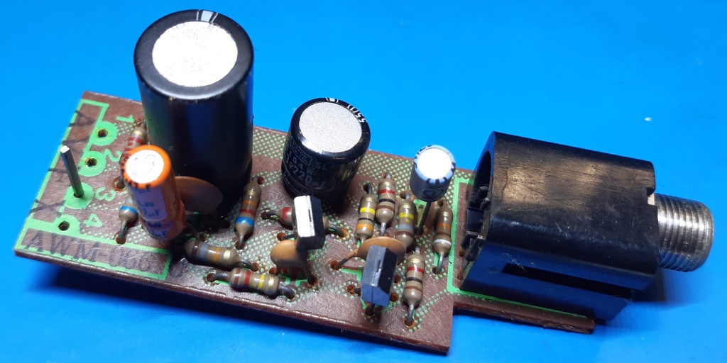
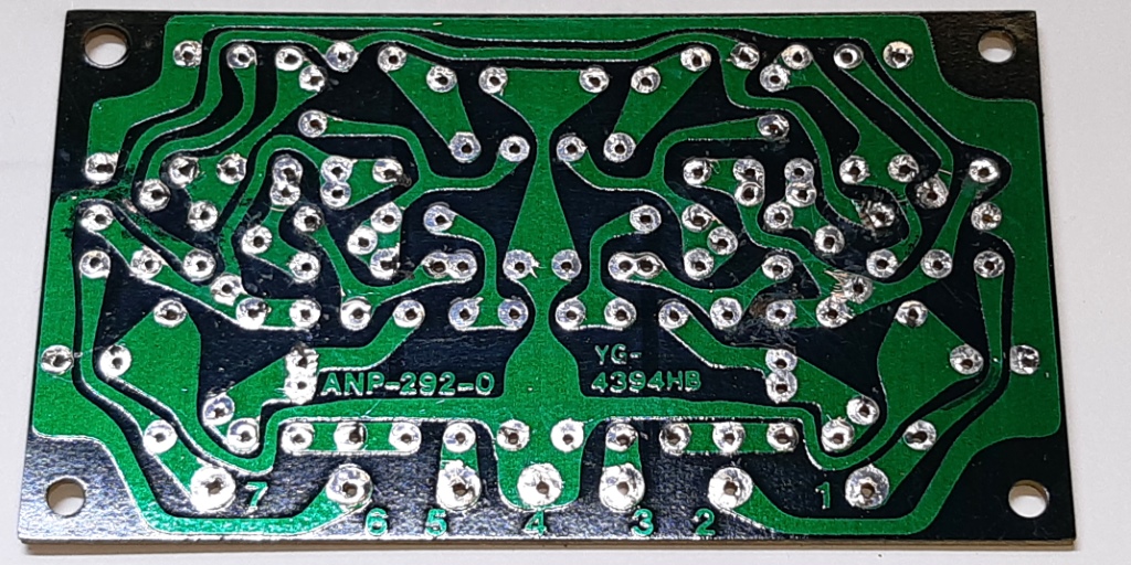
The microphone amplifier board AWM066-O This small pcb did get new transistors and some capacitors, the transistors were replaced by BC409C. Testing showed the noise level is very low. The pin marked "3" has a capacitor connected to it, but as also visible in the SX737 schematic, it "goes nowhere". Apparently this pin was initially designed to be connected to ground to migitate hum. The old situation is on the picture on the left.
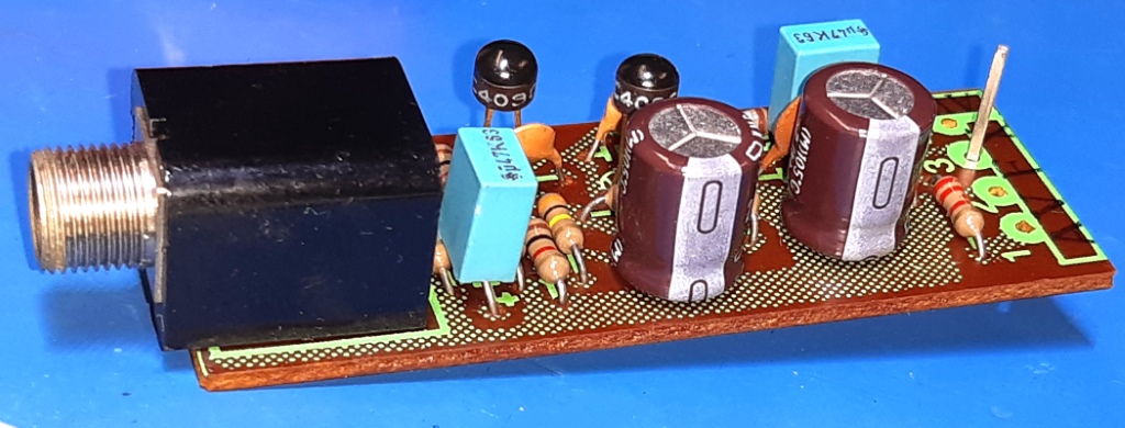
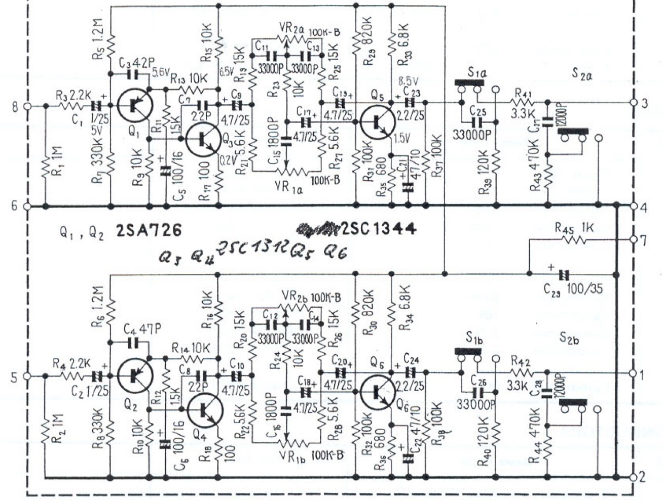
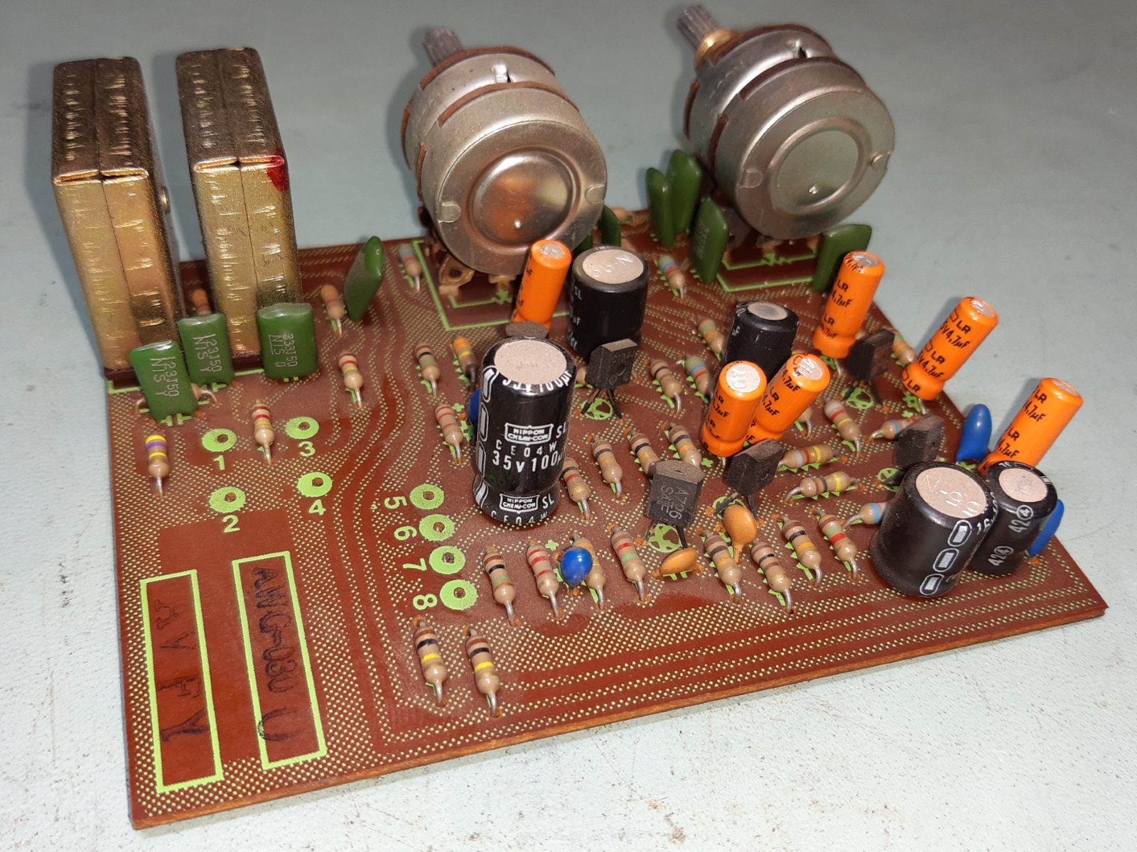
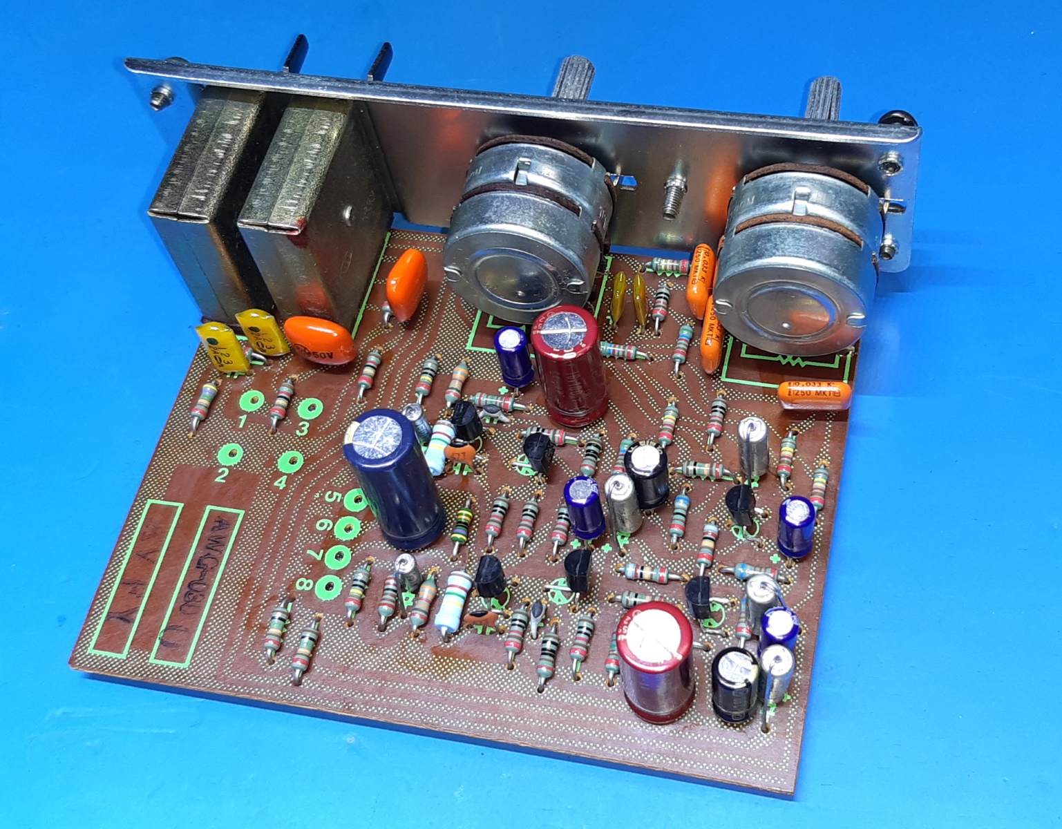
The tone control board. AWG030-O Alike some other designs this Baxandall type tone circuit has a coupling capacitor at the base of Q5 (Q6 other channel) sitting the wrong way around. Around the potentiometers is a variable DC voltage, depending on the leakage of the capacitors coupling them between the transistor stages, but as the voltage is always higher than the base connection of Q5 (6), the orientation is simply wrong. Apart from the switches and potentiometers fortunately operating flawlessly, all other parts were removed from the board. No real defects were encountered. Using mylar capacitors instead of electrolytics, there can be no problem having leakage influencing signal quality. Below is the schematic where you can check the text above, and the old situation. This circuit card was physically made by Elna according its logo on the solder side.
The new transistors used are Onsemi BC560C for PNP and Diotec BC549C for NPN transistors. Just about all resistors on this card are of the low noise MRS25 0.6 Watts type. ON PURPOSE, I modified the R11 and R12 feedback resistor from 1k5 to 2k15. The result of this will be a situation the amplifier is less sensitive, to cater for the higher average output of modern sources.
Although the result is satisfactory, the amplifier is still quite sensitive when using the cd player, you do not need turn the volume knob a lot to be loud. So basically this means I could have changed this value even more. For now, I leave it as it is.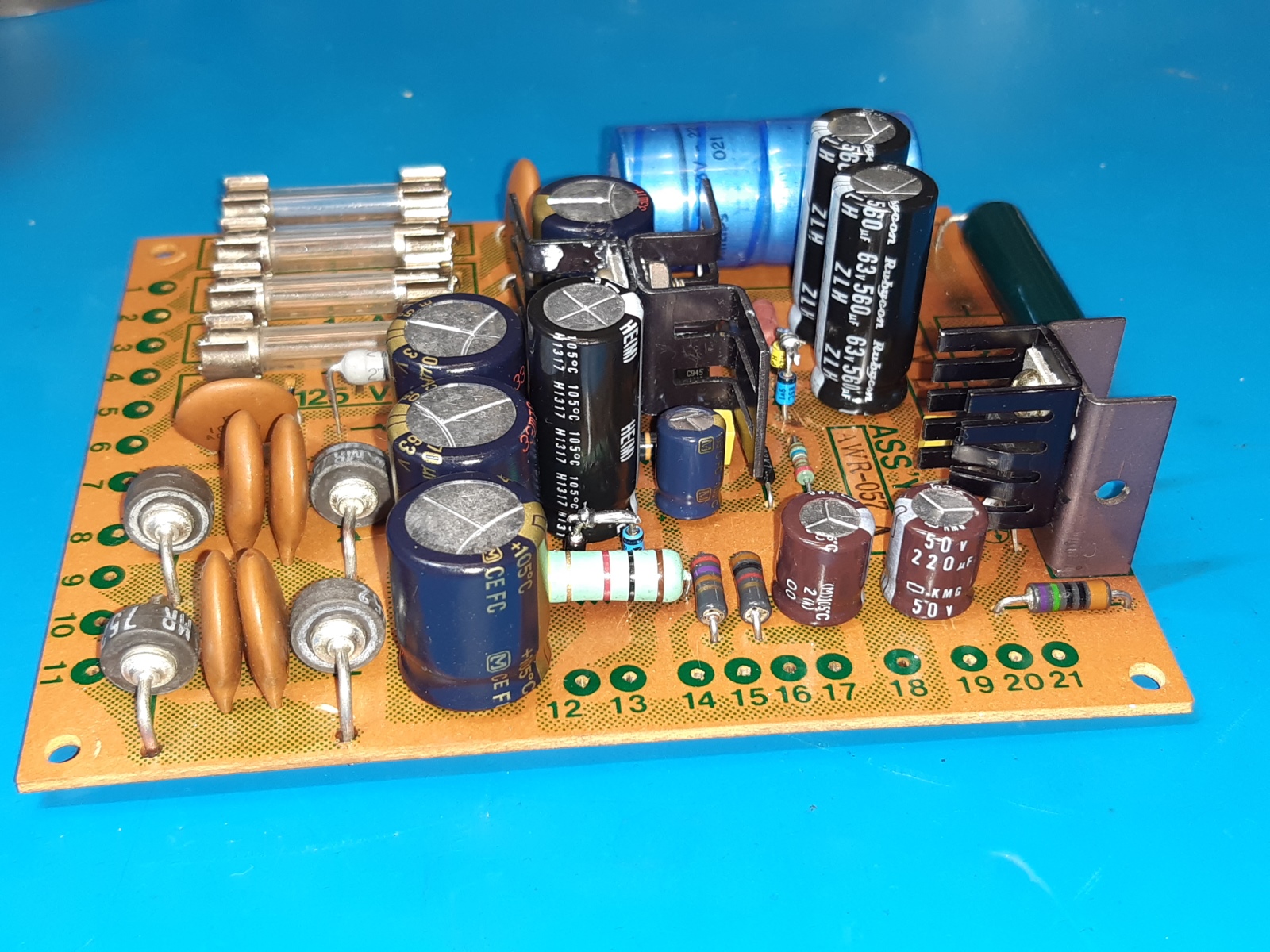
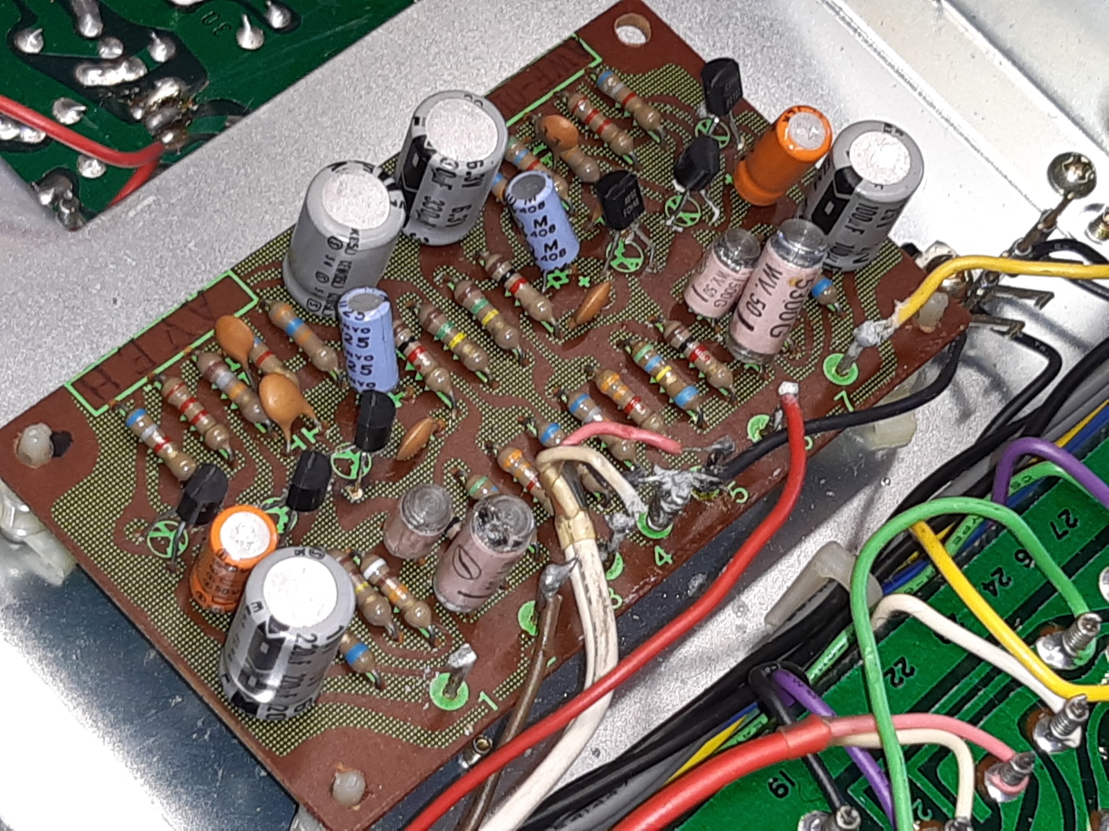
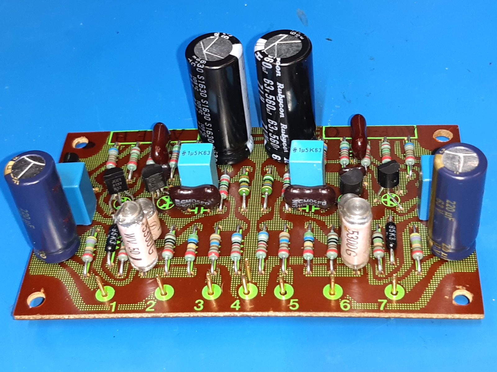
The Pioneer SX-737 RIAA Equalizer amplifier for the turntable AWF-011.
I do not know what kind of solder or flux was used by the previous owner, but it seemed almost impossible to add solder and then suck away, due to some chemical substance all over the place (this was also encountered when correcting wiring at any place solder was used afterwards)
Maybe some acid flux was used. I used IPA, Aceton, petrol to try clean the back of the pcb, and even sandpaper. Finally I could add solder, and only after adding this solder I was able to remove it again using the desoldering station. I never had such severe desoldering problems, before!
Cleaning the wirewrap pins using a sharpie afterwards, they still would not take any solder, so I decided to cut all the wirewrap pins going to this circuit card.
The previous owner of this receiver tried to update it using new transistors, they are KSA992 and KSC1845. It appears, they ALL were oriented in the wrong way in the circuit. So, it does not come as a surprise, it did not work, at all. All parts were taken off the equalizer card except the polystyrene ones which both proved very close in tolerance, including the one having some damage. I simply cut off the compromised piece of plastic, it is still a millimeter from the film construction of this capacitor.
The new transistors used are a pre-used 2SA970GR, 2SC1815 and BC337-40 on each channel, now.
Also here, premium other parts were used, and according my habit the feedback capacitor seeing a very low voltage was reformed up to its max voltage before it was used. Being in circuit it will never see reasonable forming voltage again.
Having quality goldplated connector pins and a crimping tool available, I did put male type connector pins through the circuit card instead of the wire-wrap pins.
The mating sockets are crimped on the wires and to make sure covered by a piece of heatshrink.
The connections are firm and will not loosen up by themselves.
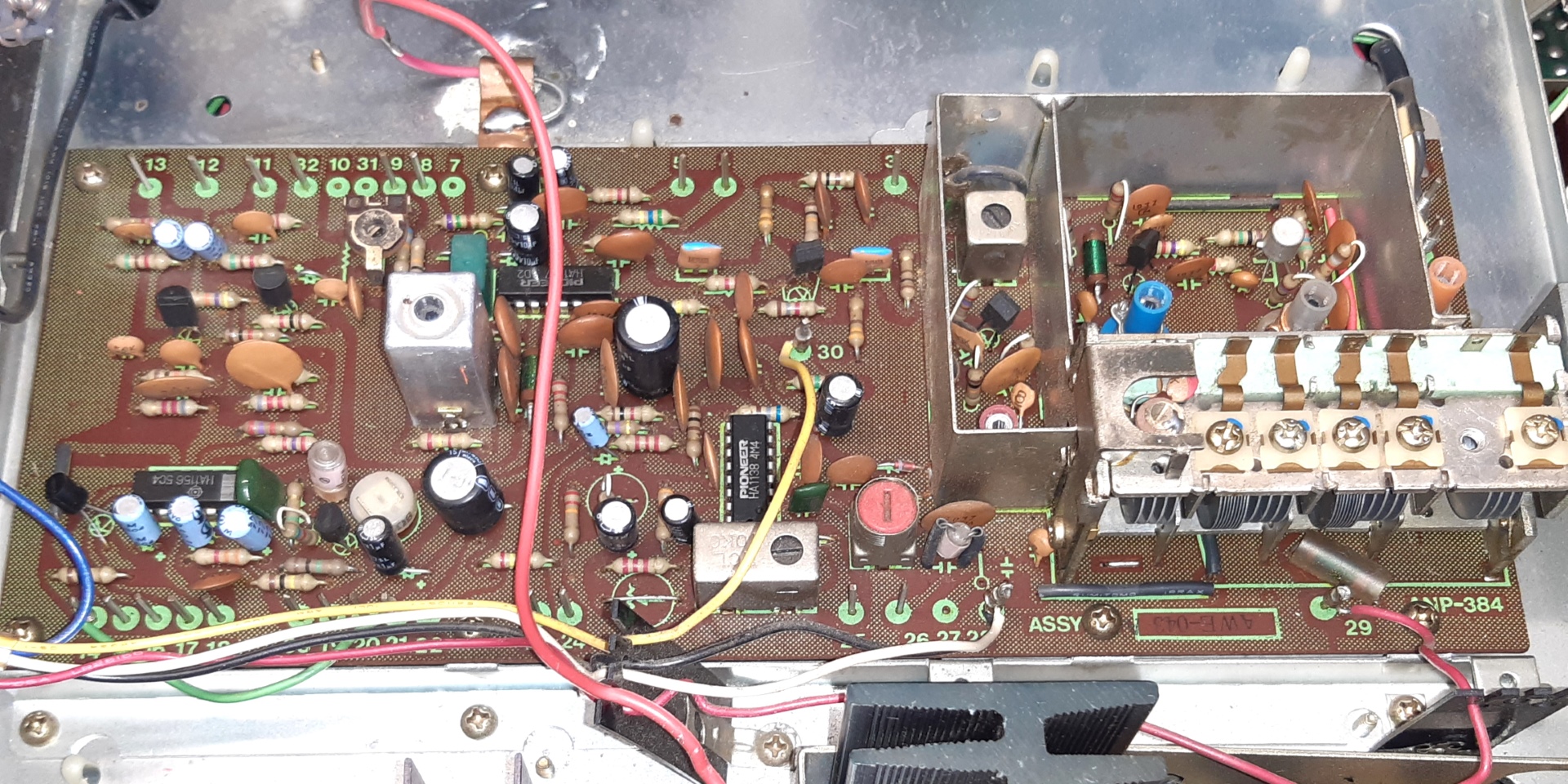
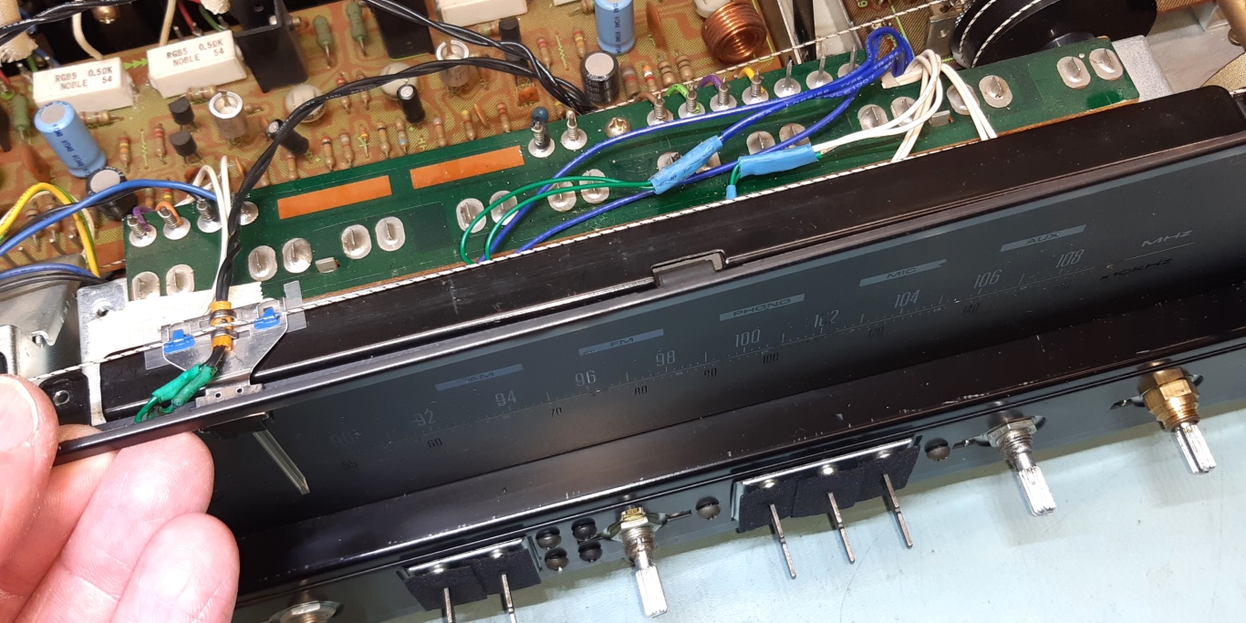
The Tuner board.
The actual FM tuner front-end is a 3-gang one, giving access to all tweakables needed.
I decided to replace all electrolytic capacitors by whatever new or better ones (like Mylar film capacitors) and replace the audio transistors.
Also the very single transistor used as an IF amplifier (in between two ceramic filters) was replaced, by (IIRC!) a BF198.
Using a Leader 3214 RF signal generator, I was able to align the FM front end. This was not without problems, as dB levels and antenna coupling was not easy, but using common sense everything went very well. The tuning range was set as well as tweaking the signal according the service manual. After this, reception is very good and the indicating meters work as to be expected, again.
The fact it went so easy was also because of the IF filtering being fixed by the ceramic filters, there was nothing there what could be detuned/needing alignment in the IF cuircuit ....
The manual procedure has to be read carefully, as the tallest coil has TWO adjustments, one from the top as well as the bottom of it!
The AM antenna can be moved away from the backplate, not that far and also not rotateable. I did not bother try align the AM tuner, as a lot of interference is around nowadays and AM is obsolete in this country. However, apart from international stations, a Dutch station was received, it seems local AM ( "middengolf" )stations are a new niche picked up by "hobby pirates".
One more thing to mention are the fact the stereo indicator is an LED right now, so the chip steering it needs less current to sink. There is no modification on the tuner card itself, for this.
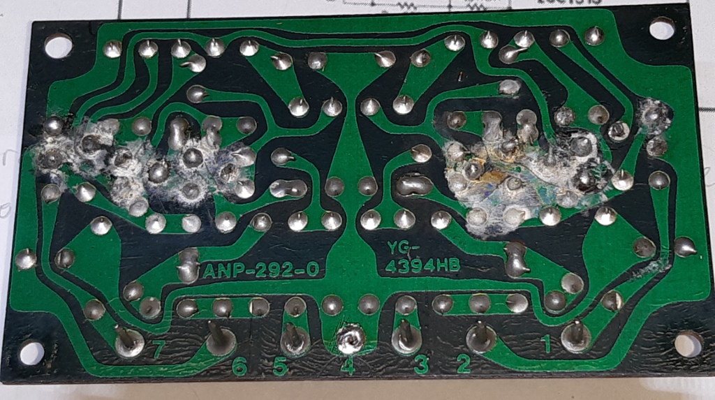
"Last but not least", there is a 220 Microfarad capacitor which damps the signal movement of the output signal meter. It is somewhat hidden on the big board containing all the selection and other switches, the AWX71 card. As all switches and potentiometers are measured being in good condition, this card was not removed. I managed to replace this capacitor by using angled pliers etc used by surgeons. For the Dutch electronic tech audience here: you can buy them at "Baco"
On the left picture is the old situation, among others you see some little Sanyo solid-aluminium capacitors which are always more or less electrically leaky.
On the picture visible on the right the recap was done, the metal axial capacitors are Sprague axial Tantalum ones, and most other small value capacacitors are replaced by rectangular film capacitors.
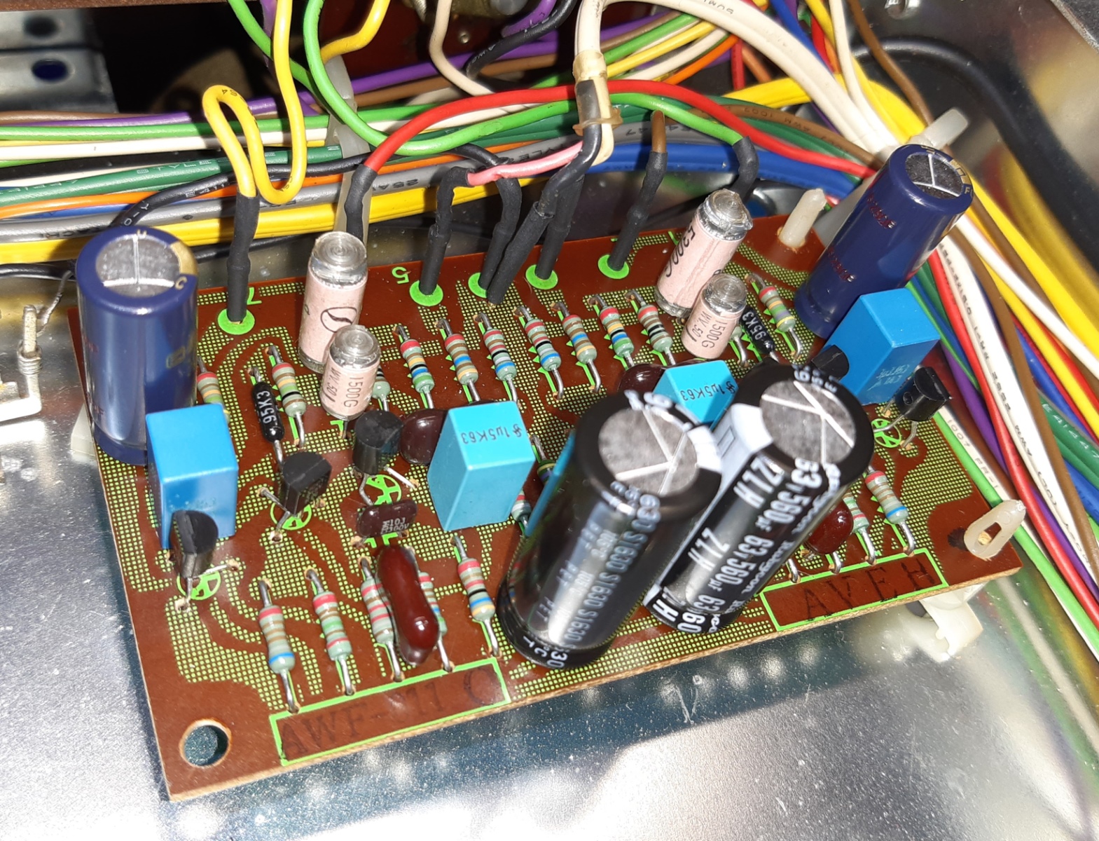
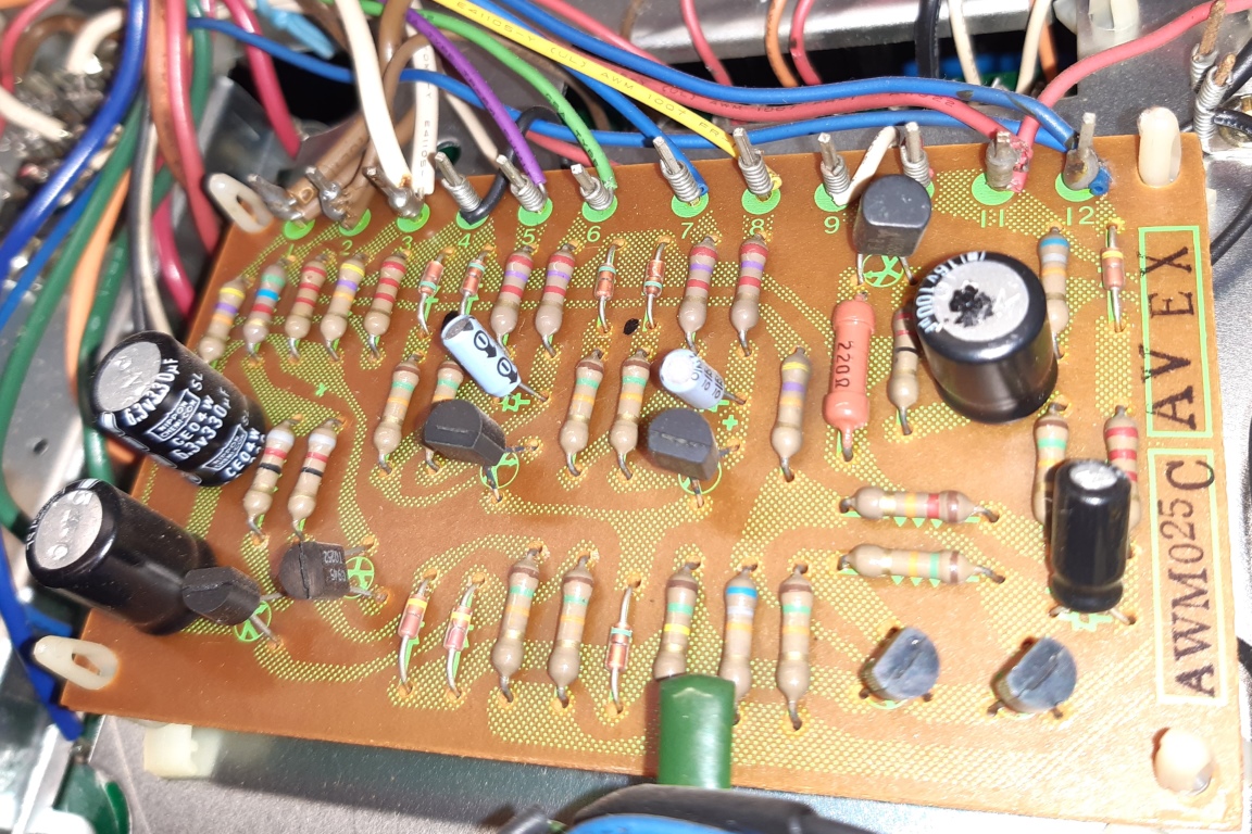
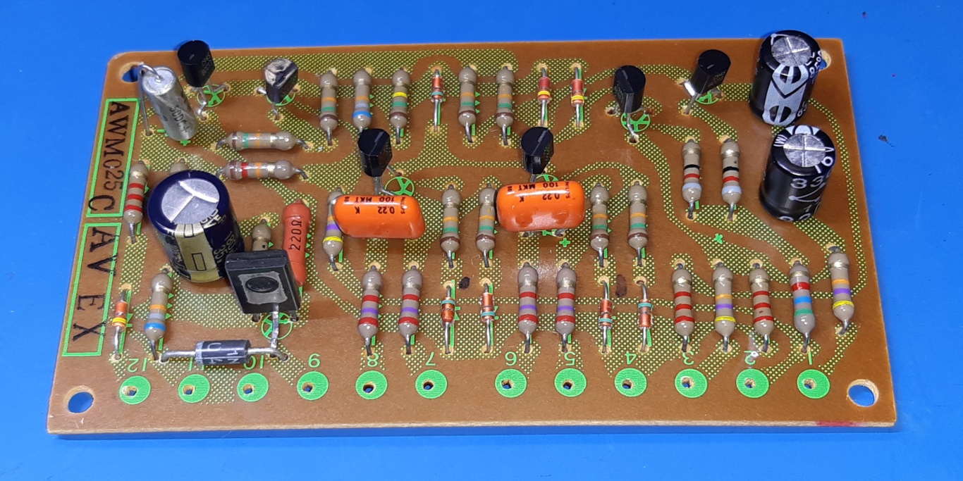
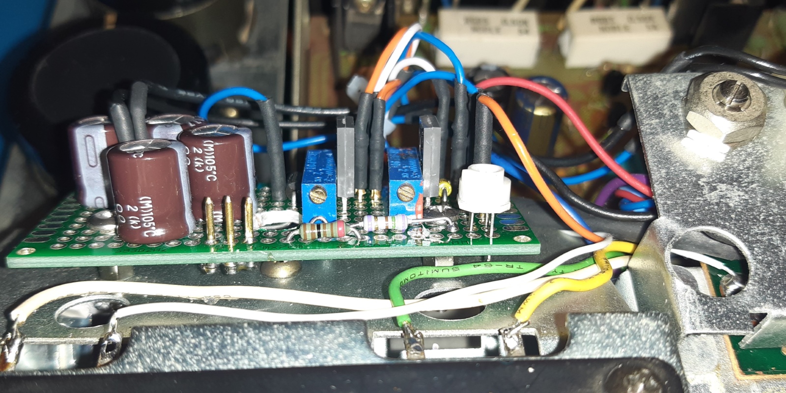
The amplifier protection board AWM025
The protection card is the first to be removed IF one wants to remove the power supply card and removing wirewrap pins, so this was one of the first taken out and refurbished.
The electrolytic capacitors are renewed. C6, important for the timer, I increased to a 180 Microfarad one making the relay "on" timer a bit slower.
DC sensing transistors are KSP42 now, the Q3/4 pair is selected KSC945, Q5 a KSA733, Q6 a KSC945, and Q7 a BD137. A protection diode is connected over the relay contacts output, now.
The old situation is on the picture on the left, the new on the right.
The receiver lighting.
Wanting to make sure the lighting works as I desire I decided on an adjustable scale and meter lighting, as I do not like some LED tubular replacement lamps I have.
Although this is always a hassle I feel the result is better.
I regard the lighting as four pieces for the refurbishing: The backlighting of the scale and meters, the source select indicators, the tuning needle light and the stereo indicator.
I decided to leave the tuning needle light as it is, so the actions to be done are the scale and meters section, a separate solution for the source select indicators above the scale, and a modification of the stereo indicator.
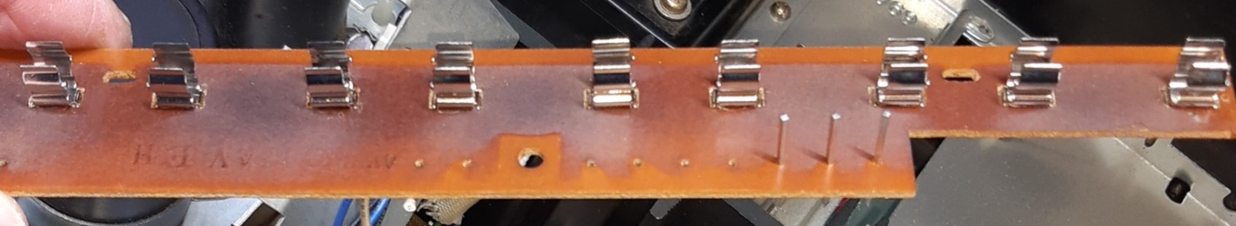
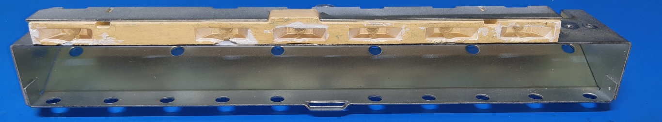
The picture of the old situation shows, some work was done on the source select lamps already, but as usual it was again partly defective. The reason for this is the fact you can not buy good quality lamps, anymore.
On the meters housing, the lamp sockets were removed, and on the circuit card holding the tuner scale lamps I removed the lamp clips from the pcb.
Having 5 mm LED's available, I drilled out the holes on the already compromised and brittle sand colored material holding the selection lamps, put a small layer of glue on it to keep things together and added some white paint in the openings for extra reflection.
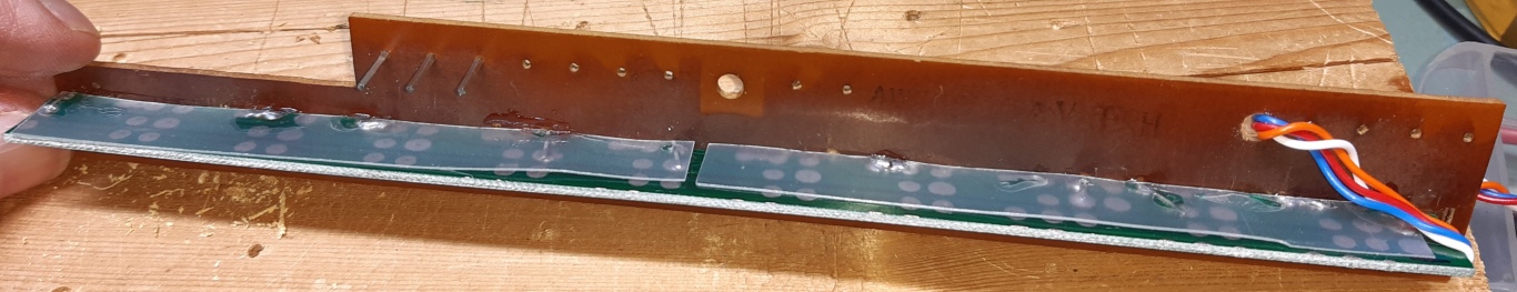
I used a RGB strip mounted on a piece of unused epoxy pcb, and I mounted it at a 90 degrees angle on the tuner scale lamp pcb. A piece of adhesive strip is inside the meters housing also.
I constructed a circuit on a stripboard driving the RGB led strip, using the design I made for the Akai AA6600. I may put a schematic here later, as also potentiometers and resistors for the stereo and source select lamps are in the game.
The "naked" picture of this module does not show those additions, yet, the other shows the resistors and white trimmer for the source selection indicators which is routed to the common tab of the source selector switch lighting part of it, as well the top of a screw-mounted metal trimmer for the stereo LED on the metal strip dividing the lighting module from the tuning needle lamp cable. The metal strip exists because of this cable moves with the needle.
The tuning "needle" is the only incandescent lamp remaining.
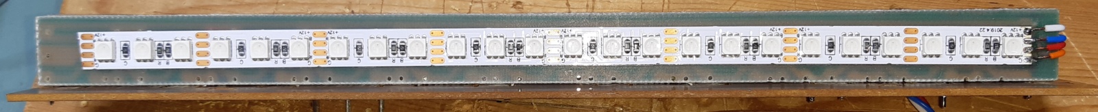
These are xamples of the color range the new lightstring could provide. Steering the RED connection of the RGB strip was omitted, as testing also proved the blue graticule itself blocks red light.

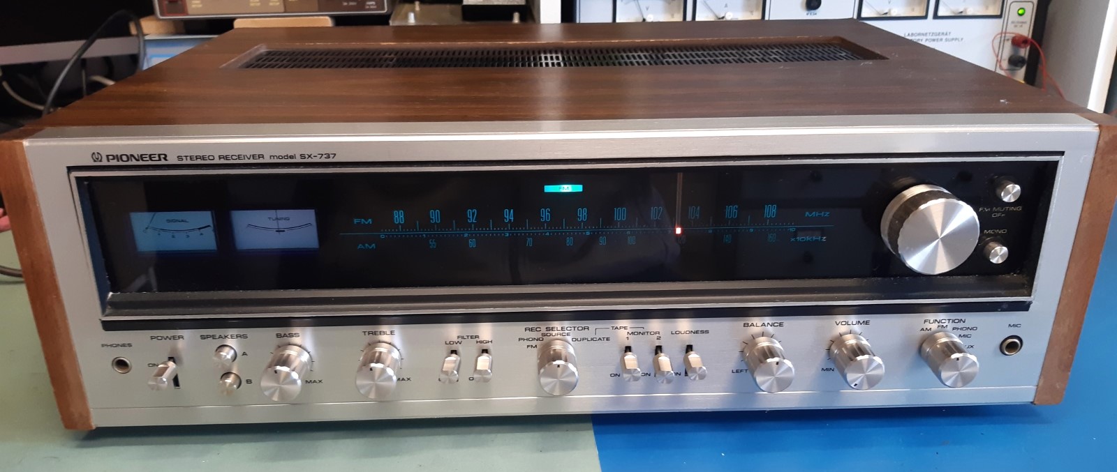
The front of the receiver.
Showing off, the Pioneer is somewhat larger comparing to the Akai.

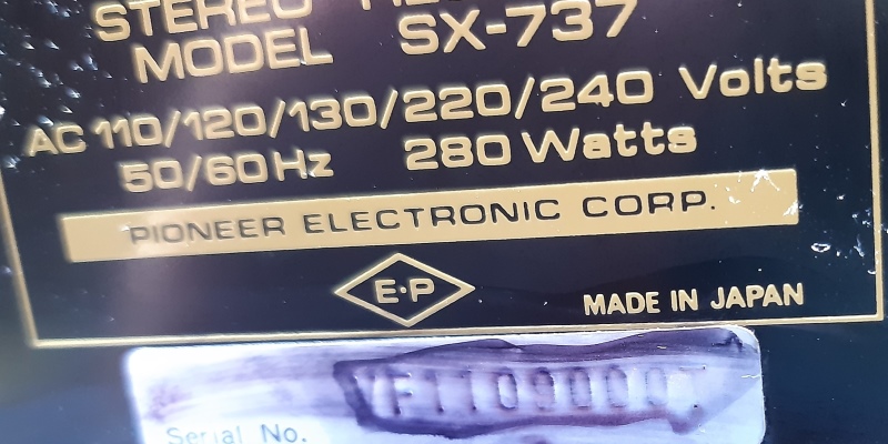
The serial number on the back was almost invisible.
To identify I used a marker and cleaned afterwards. The number is rather odd having a T at the end, compared to other info available on the "audiokarma" website.
Anyway, according serial number info this receiver was made june,1975, so it is over 50 years old.
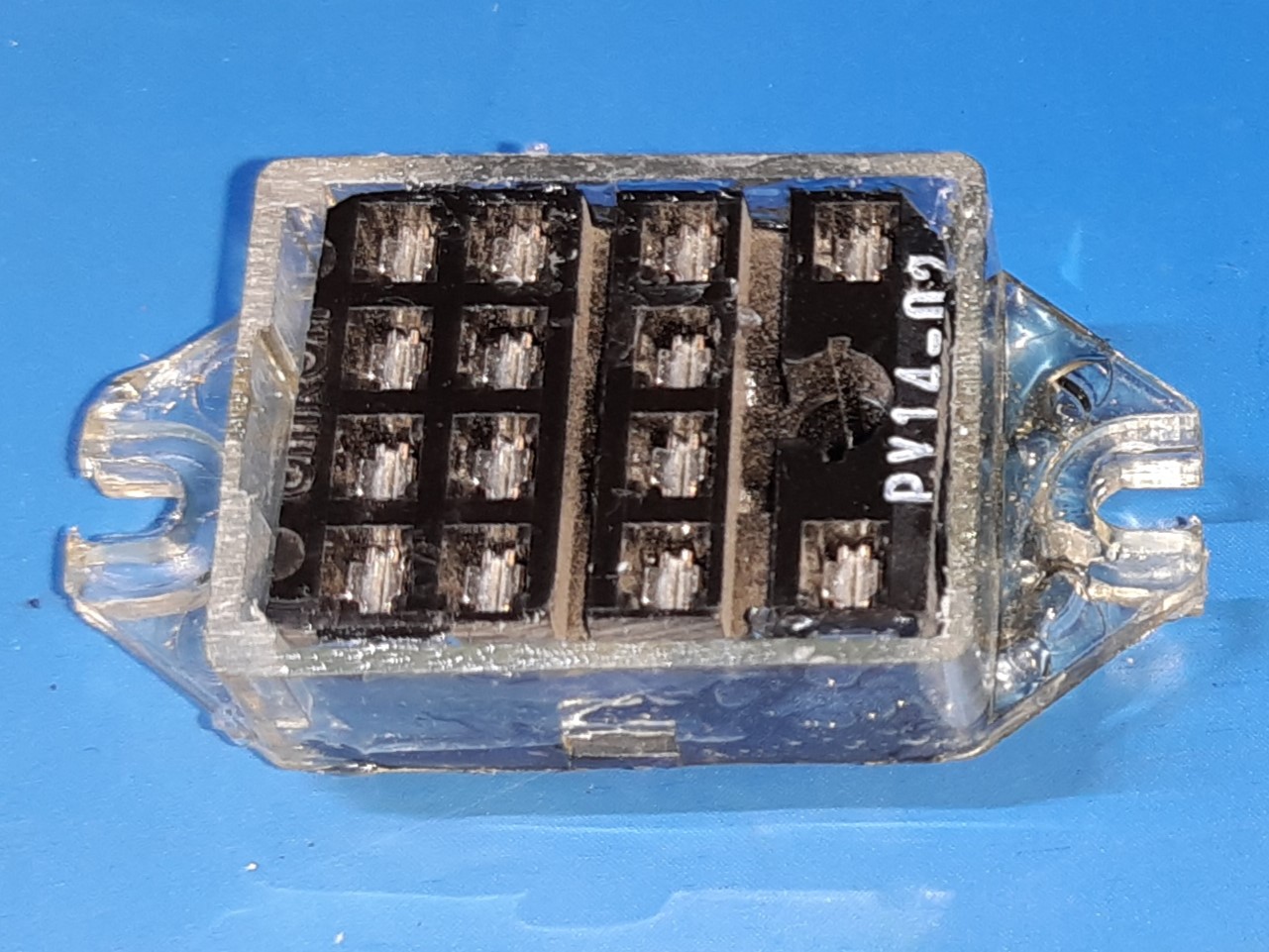
Also a new protection relay was mounted, I used part of the plastic of the old relay to make a relay socket, as a new relay replacing the old one nor a relay socket having the mounting holes are available on the market, anymore.
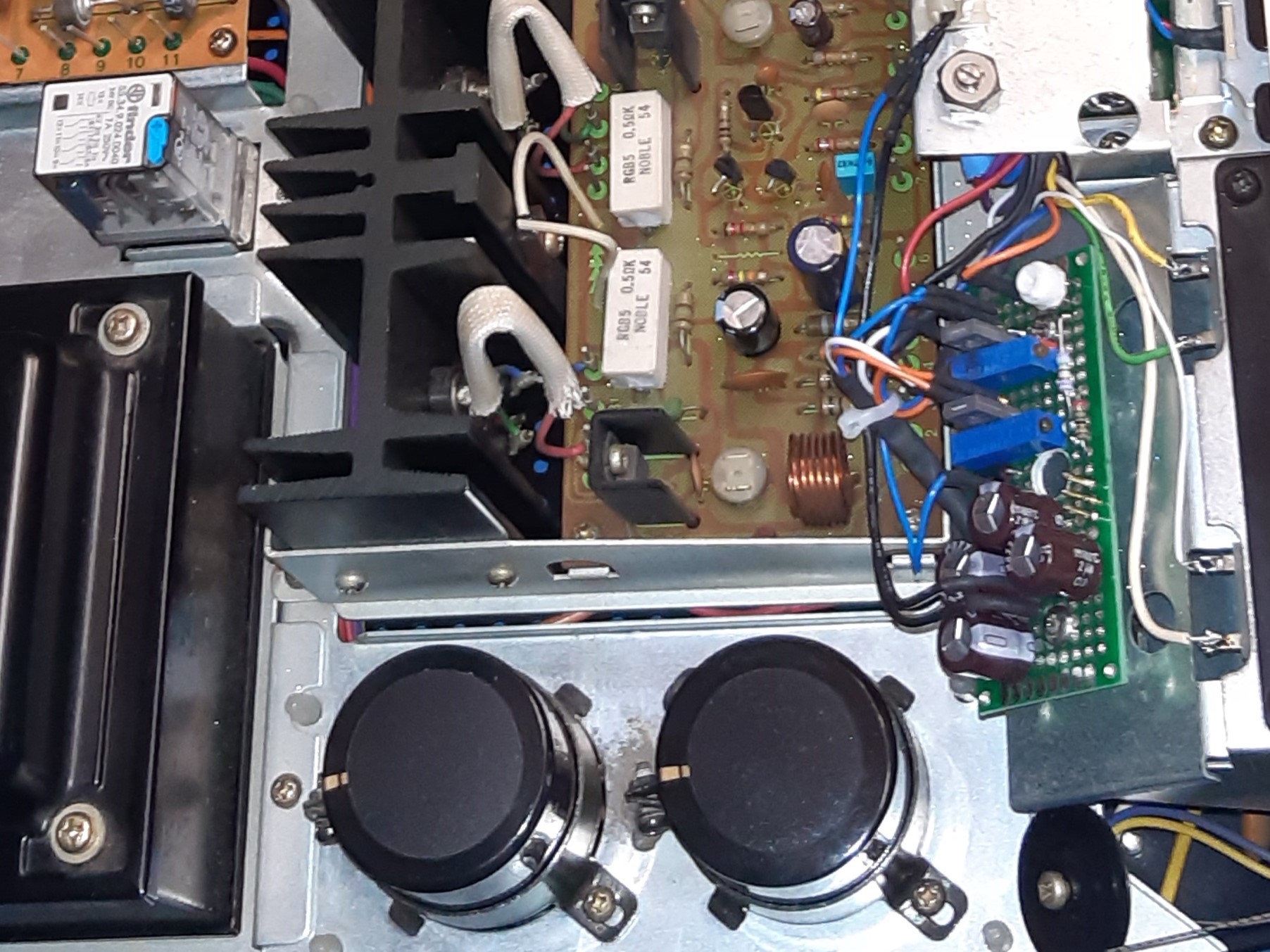
The third pictures gives a peek at the lighting module, the new power supply caps, and the new relay which is positioned on the top left of it.
The bottom of the receiver.

The top of the receiver.
Ga naar Gerards homepage / go to Gerards main page ---->>> ![]()