Ga naar Gerards page / go to Gerards other pages ---->>> ![]()

Pioneer SA700 refurbishment / recap / modifications
I sold this one to a nearby collector, it creates room for a new fun piece and money to buy parts!
![]() Gemakshalve is deze pagina alleen in het Engels geschreven.
Gemakshalve is deze pagina alleen in het Engels geschreven.
![]() This page is written using English language only.
This page is written using English language only.
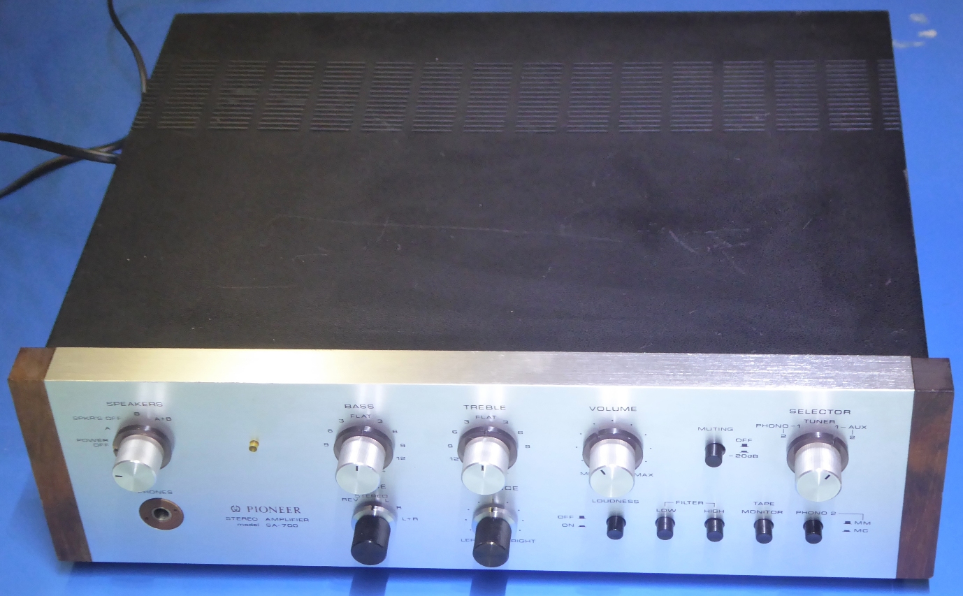
This Pioneer SA-700 was bought on the Dutch Marketplace end of 2021.
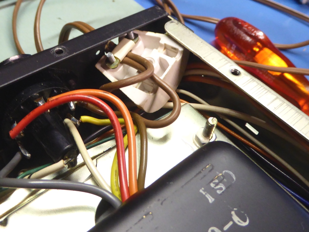
It was supposed to give a soft rumbling sound when no signal was present, and advertisement pictures already revealed a missing strain relief on the mains cable.
Inside, some "interesting repairs" appeared. Of course, most obvious was half of a mains plug, which was clamped on the mains lead, to avoid this cable being pulled out!
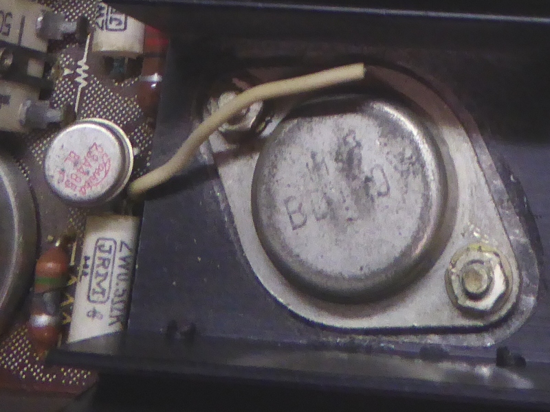
One channel had BD130 transistors, which had their leads rather poorly soldered.
The other channel had its driver transistors replaced, they had chimney-alike heatsinks.
Both channels did have two series diodes bypassing the bias diode, in fact this made the amp a class B amp, making sure to have more than enough distortion ;-)!
Still, the amplifier was "more or less" "working good" on low volume as advertised, (just leave out "more" and "good").

Some situational pictures of this butchered amplifier:
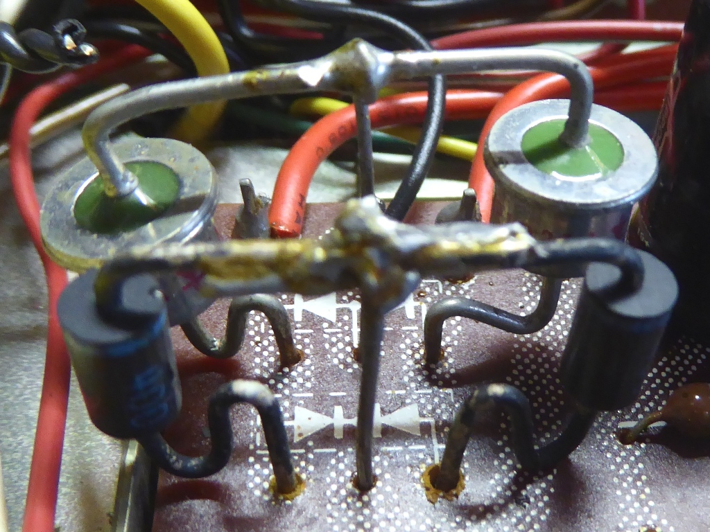
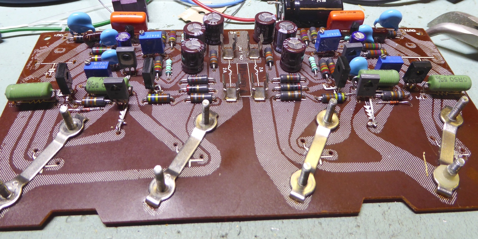
At first,a hilarious picture of "The very interesting strain relief solution", and one of the bottom side ot the main amp. The two blue pieces are diodes bypassing the temperature pickup diode and trimming potentiometer...
Im am very impressed by this type of ingenuity, I would not feel safe having the one who did this work on the brakes of my car....
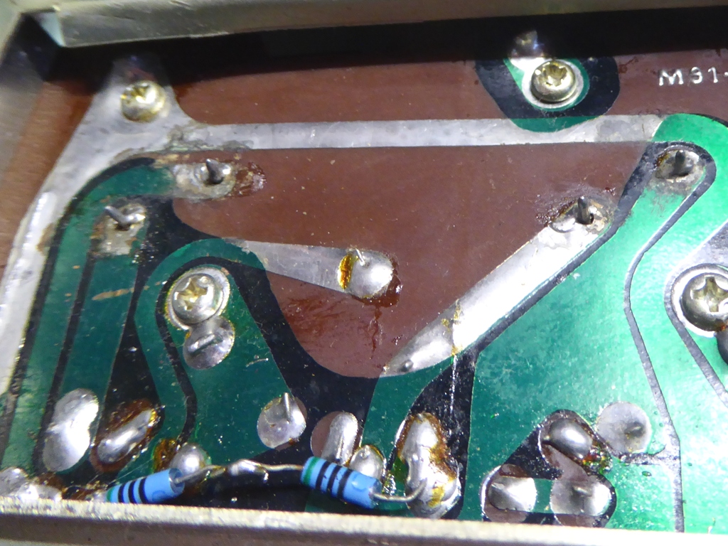
A replacement of two of the rectifier diodes on the power board, and there appears a burnt resistor in part of the main amplifier (bottom left on the picture on the right).
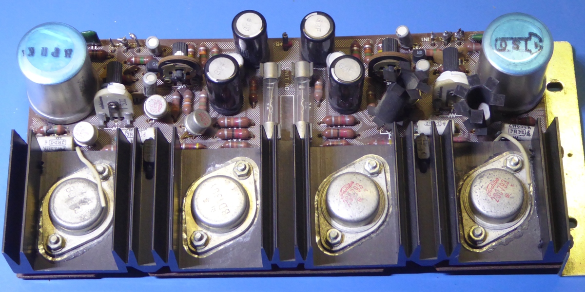
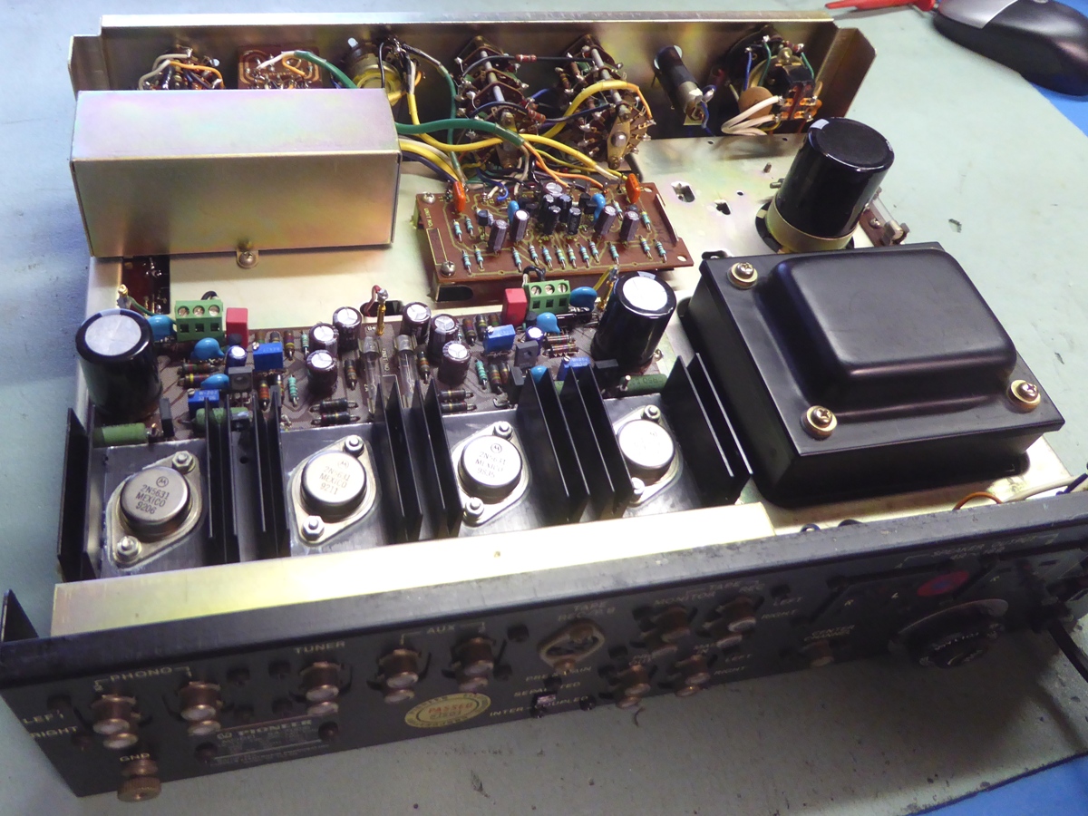
The main amplifier channels reburbishment
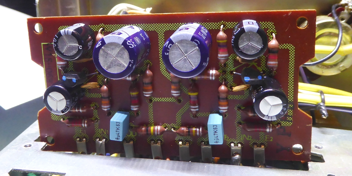
Pictures of the amp circuit card as it was.
As the temperature sensing diodes were 0.3 Volts apart when testing, they were not trusted, there was too much of a difference. I did choose for a bias multiplier arrangement using a BD329 TO-126 transistor.
Those BD329 are mounted against the heatsink, one of the legs of them go under the heatsink into the holes where the diodes once went.
Speedup capacitors mounted over the transistors are at the bottom side of the circuit card, there was no room for them on top. (Although, "speedup" may not be the proper description, it is just enhancing signal transition)
Next to those transistors little diodes can be seen, parallel to the 180 Ohms resistor. This are "Baxandall diode" arrangements, I put in with the intention of further reduce distortion.
A lot of info can be gathered providing a search engine "baxandall diode modification" as input on the internet.
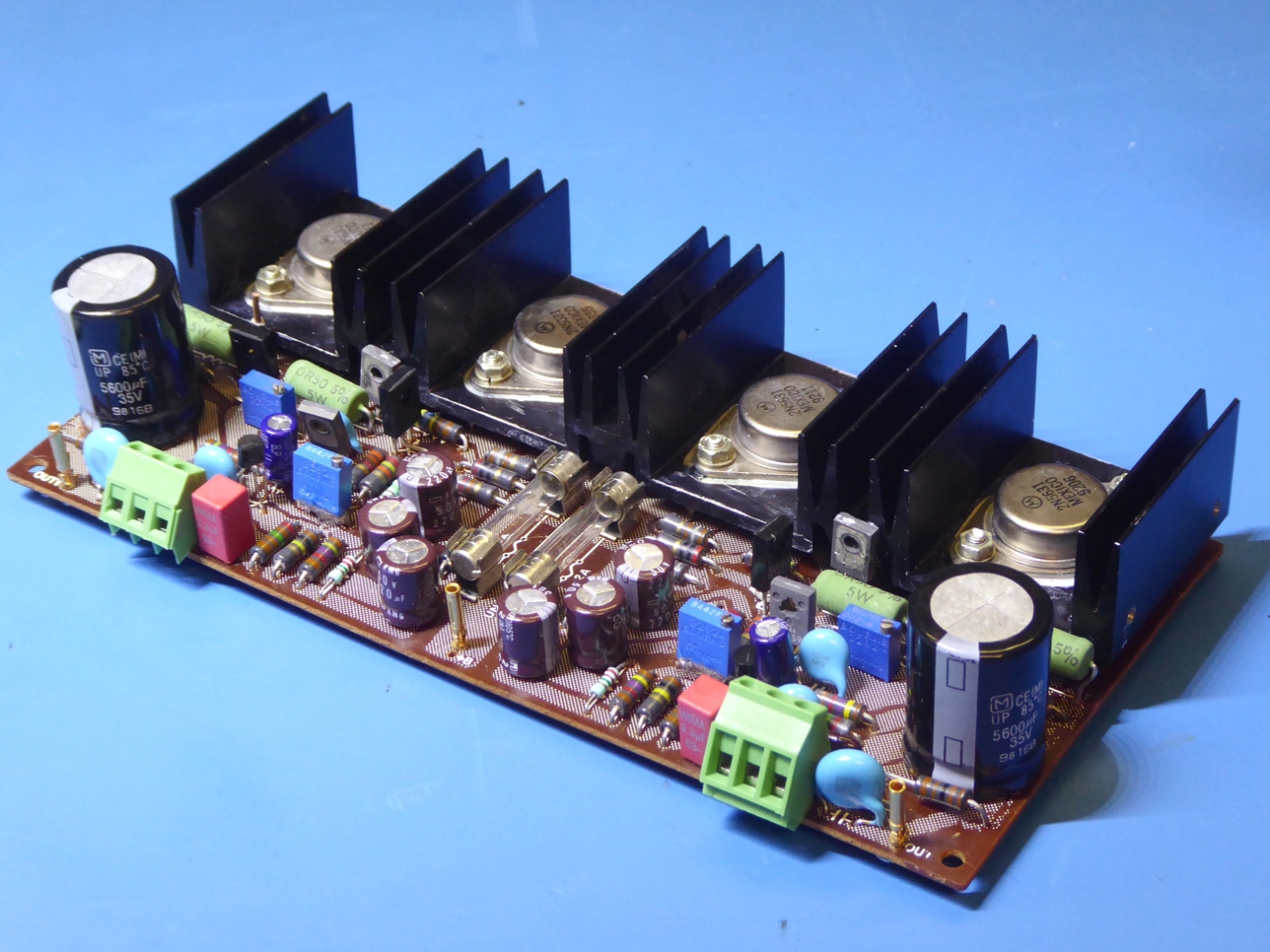
Rebuilt main amplifier circuit card.
The big output transistors are way overkill, I am pretty sure this makes them more reliable than they ever were. They are a higher voltage version of the ones originally used in Tandberg TR2075
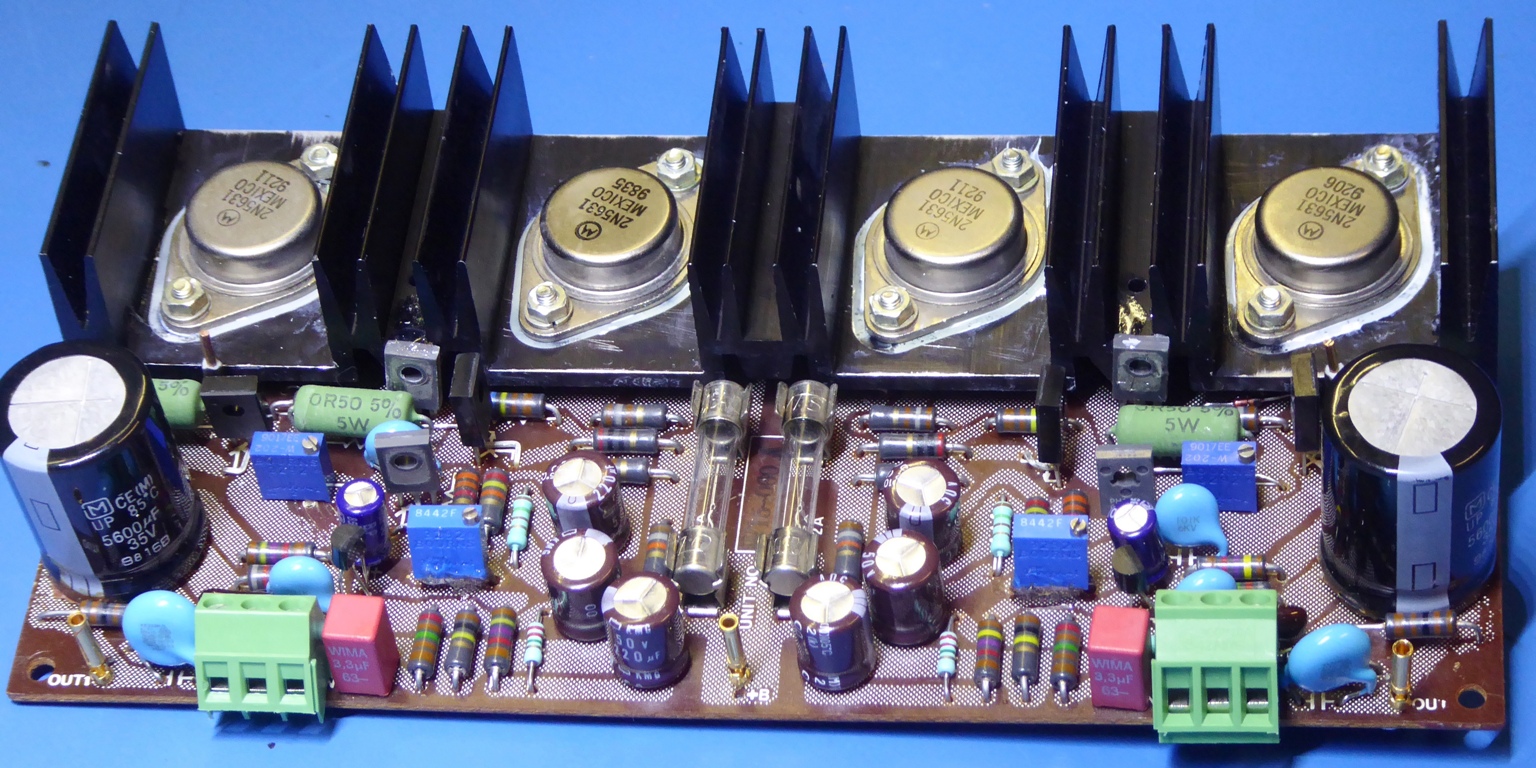
Most resistors used are half watt Corning GlassWorks metal film ones which have a real glass body and copper bushing/leads, these are almost nowhere to be found anymore! They are the commercial milspec RN60D equivalent, seems the only info to be found in the CGW leaflet. Specs are same but RN60D uses printing for its value instead of color code.
I used larger capacitance output capacitors of 5600 microfarad, it makes sure the "cap coupled" amplifier will also produce the low "bass" tones effortly when low impedance 4 Ohms loudspeakers are used instead of 8 Ohms.
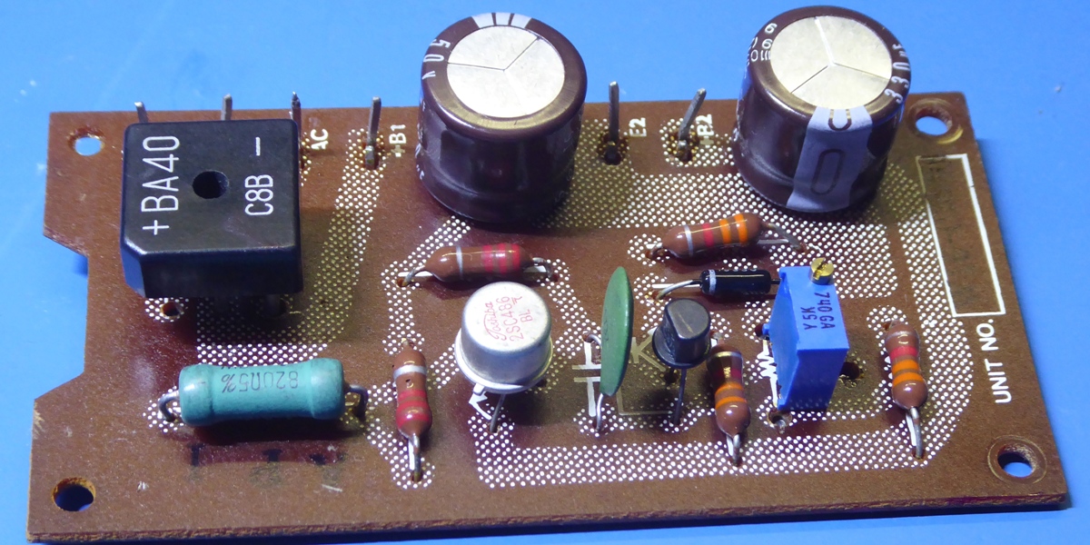
Power supply circuit card.
The power supply circuit card provides the rectifier and the 25 Volts regulation to provide power for the pre-amplifier.
The rectifier was replaced, it is good to be a sturdy one, as the main 2200 Microfarad smoothing capacitor is replaced for a 10000 Microfarad one.
2200 Microfarads is really rather low, 10000 is more than adequate for a 2 x 27W amplifier.
The original trimming resistor appeared to be the very cause of the "rumbling" sound if the amplifier was without signal.
Phono Moving coil preamplifier, which is switchable from the front panel.
Apart from getting some new capacitors, this one transistor amp, having blue-dotted transistors, was untouched. It is presumed these dotted transistors were especially selected.
It also appeared rather tricky to loosen the wires, so the card was not taken out of the amplifier, at all.
On this card, Pioneer used the 5-band color code resistors, which are supposed to be low noise.
It should be noted, a MC preamp circuit was very odd during those days, and usually people ended up buying a very expensive "pre-pre". Even my Kenwood 700C, which was considered the extreme high end during those days, did not have the MC feature.
Phono Moving Magnet preamplifier.
Apart from new electrolytic capacitors, this one did get new transistors. Four resistors were replaced by metal film types, on spots where they could be contributing to noise.
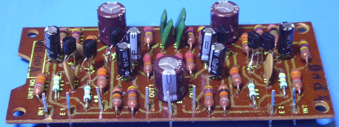
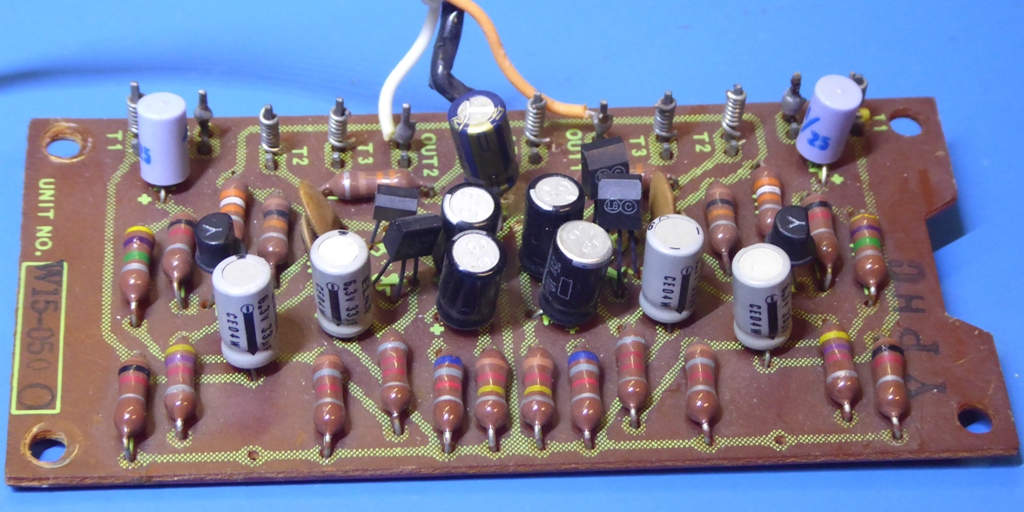
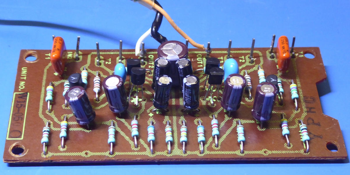
The Control preamp W15-050
The control amp did get new capacitors and transistors, except for the 2SK17 jFETs.
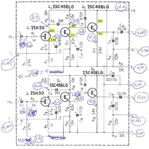
It appears Pioneer made the very same mistake as on the very same circuit board in my SA-900. They used a 33 microfarad 6 Volts capacitor on a spot where close to 10 Volts actually resides and a 4.7 / 25 Volts is specified; C7 (17 on schematic) and C8 as can be seen on the schematic here.
The control amp did get new Philips metal film resistors also, to minimize noise.
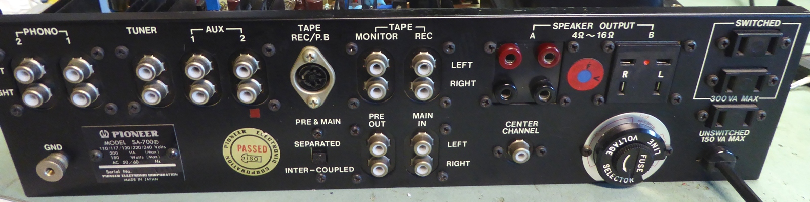
The pioneer sa700
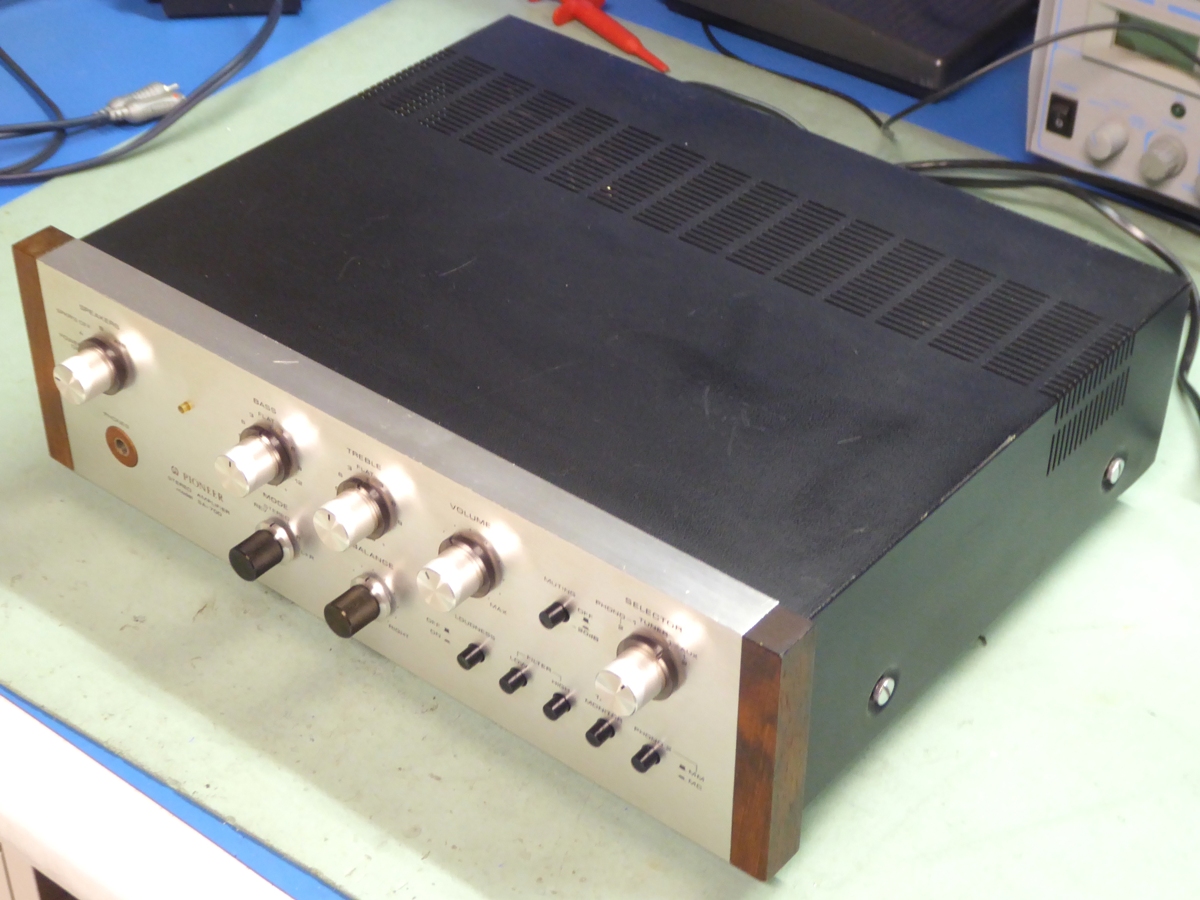
Banana sockets were used for the loudspeakers "A" selection setting, as the amp may be sold, since Pioneer loudspeaker plugs are scarce and tend to disappear.
Ga naar Gerards page / go to Gerards other pages ---->>> ![]()