

Pioneer SA1000 restoration / restauratie, 2026
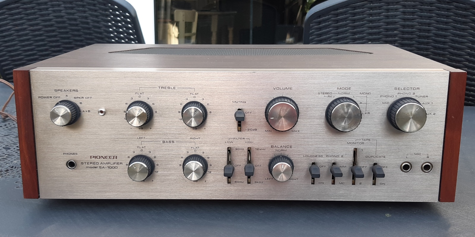
This SA1000 is for sale in the Netherlands, fixed price 500 Euros, cash and Local Pickup Alkmaar area as I do NOT ship, note is has some visible small cosmetic flaws.
Gemakshalve is deze pagina verder in het Engels geschreven.
 This page is written using English language only.
This Pioneer I bought on "Marktplaats", I always wanted this iconic piece.
Advertised as not working, an obvious thing was missing metal plating and other things.
I also bought a SA600 and SA800, both had their faceplates text faded out, worse than this SA-1000
I decided at least preserve the SA1000, planning to use part from the other units if needed.
Having all three together, I managed to have enough knobs and metal knob caps (most old Pioneers lack one or more caps...)
Notice: the wooden cover of those amplifiers is the very same.
As "just about nothing worked" of this amplifier, I decided on a total refurb, which included total cleaning and restuffing of the circuit cards.
The biggest problem with refurbishing this particular amplifier is the fact the wirewrap pins can NOT be removed from the circuit cards without damage.
Another issue is the fact there are TWO different schematics and components layout of this amplifier on the internet, both NOT 100% covering all items in the respective amps they represent. THIS SA1000 is "something in between", so there will have been several modifications during the production process and I needed both service manuals to get the complete picture.
This page is intended as a hobbyists showcase for repair or refurb, assuming the reader has all technical info to be found on the internet at hand, already.

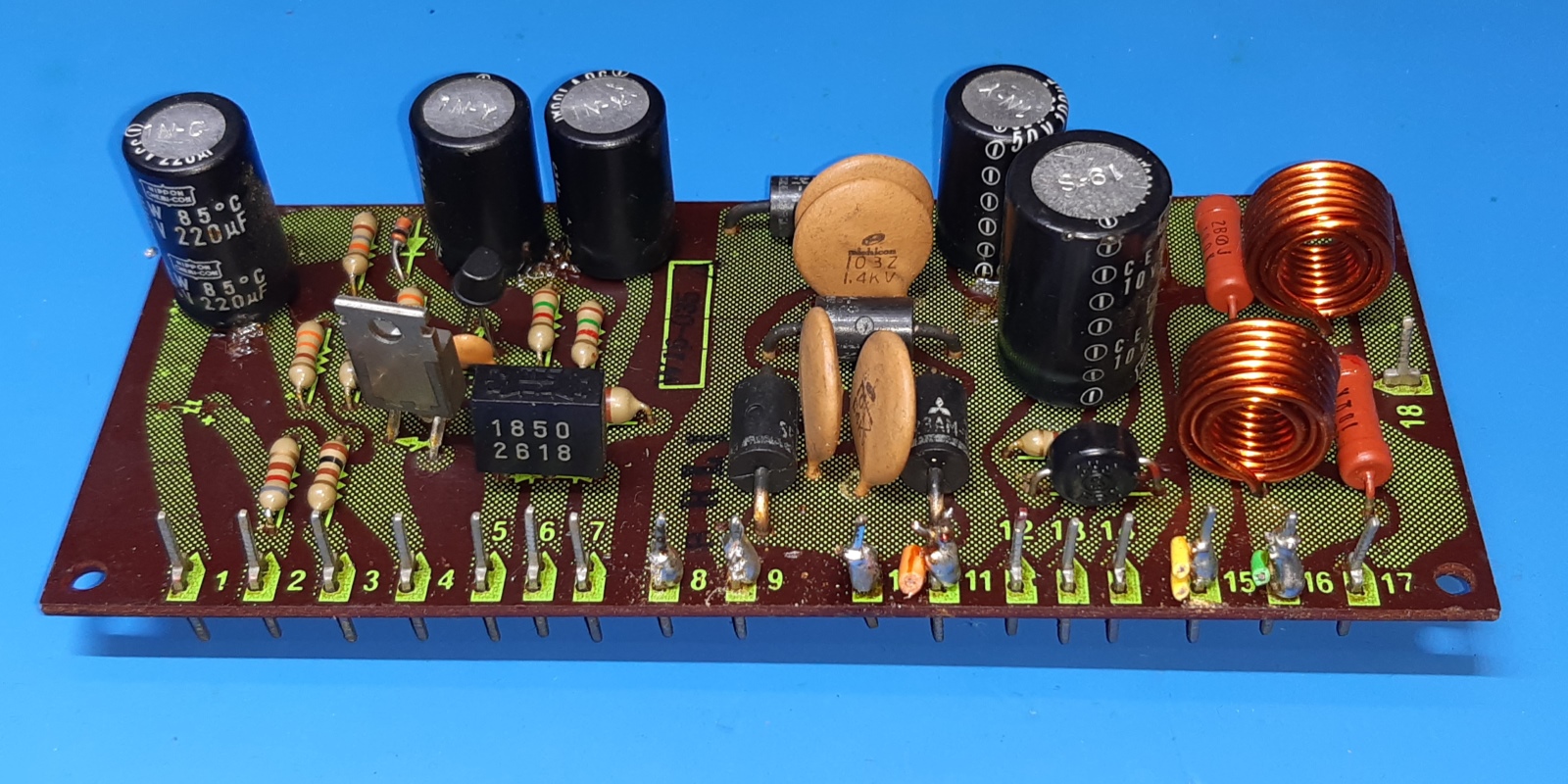
The pioneer sa1000 power supply card, W16-035, and other power supply support.
The power supply card contains the rectifiers for the unregulated voltages, some small smoothing capacitors and a regulator circuit supplying 35 Volts regulated and derived voltages.Additionally, the Zobel network coils and resistors for the loudspeaker outputs reside on this board.
Some of the components were renewed, some remain.
The off-board fuses looked dirty, their sleeves were tacky, I decided just replace those wired fuses by removable ones, making it look more neat en being more flexible if there would be need to replace a fuse.
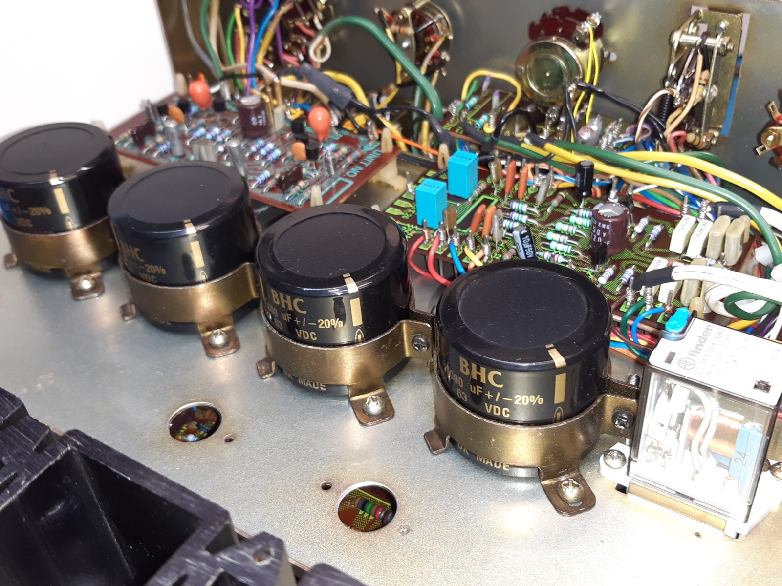
The four big Elna 4700 microfarad capacitors were replaced by nice BHC (Kemet now) type ALC10 10000 microfarad ones. I evaluated the power diodes to be able to handle the extra initial power-up current.
In general, just about all power supply related electrolytic capacitors were replaced by new ones having bigger capacitance. Below is the old situation.
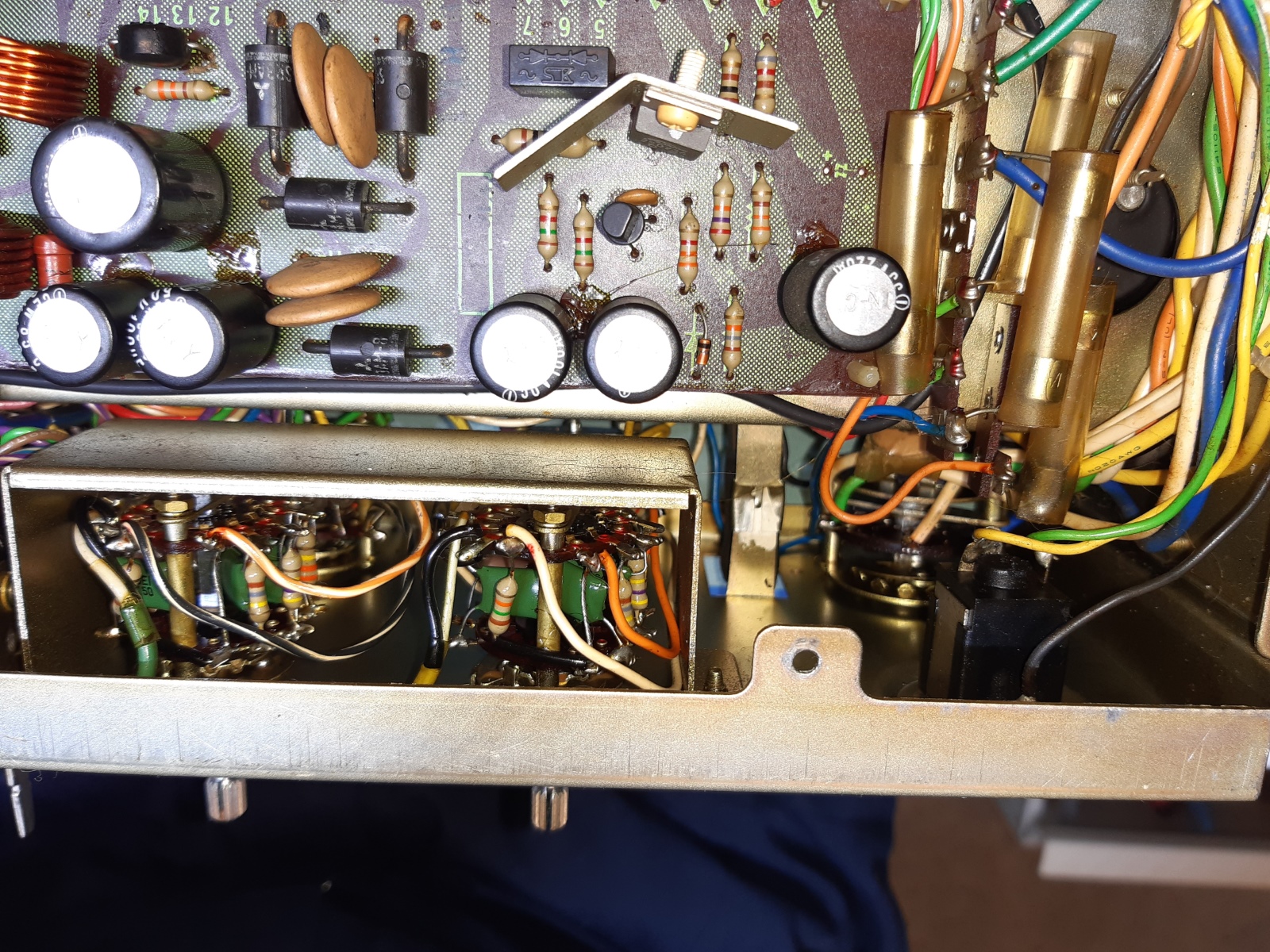
The new situation showing the partly repopulated card, and a repurposed old fuse bracket carries the new normal type fuses.

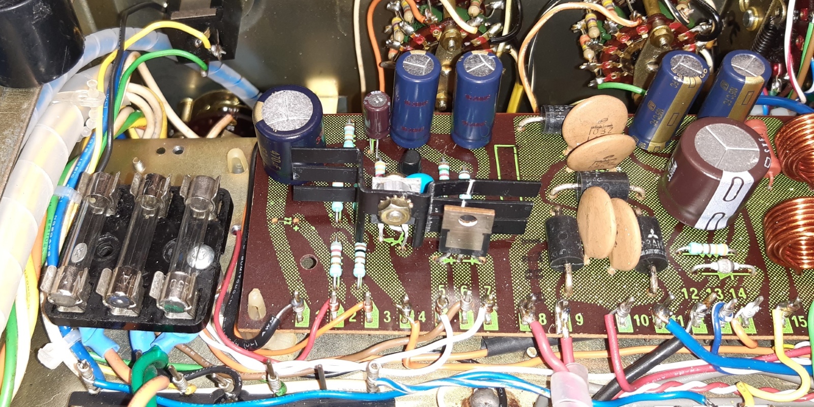
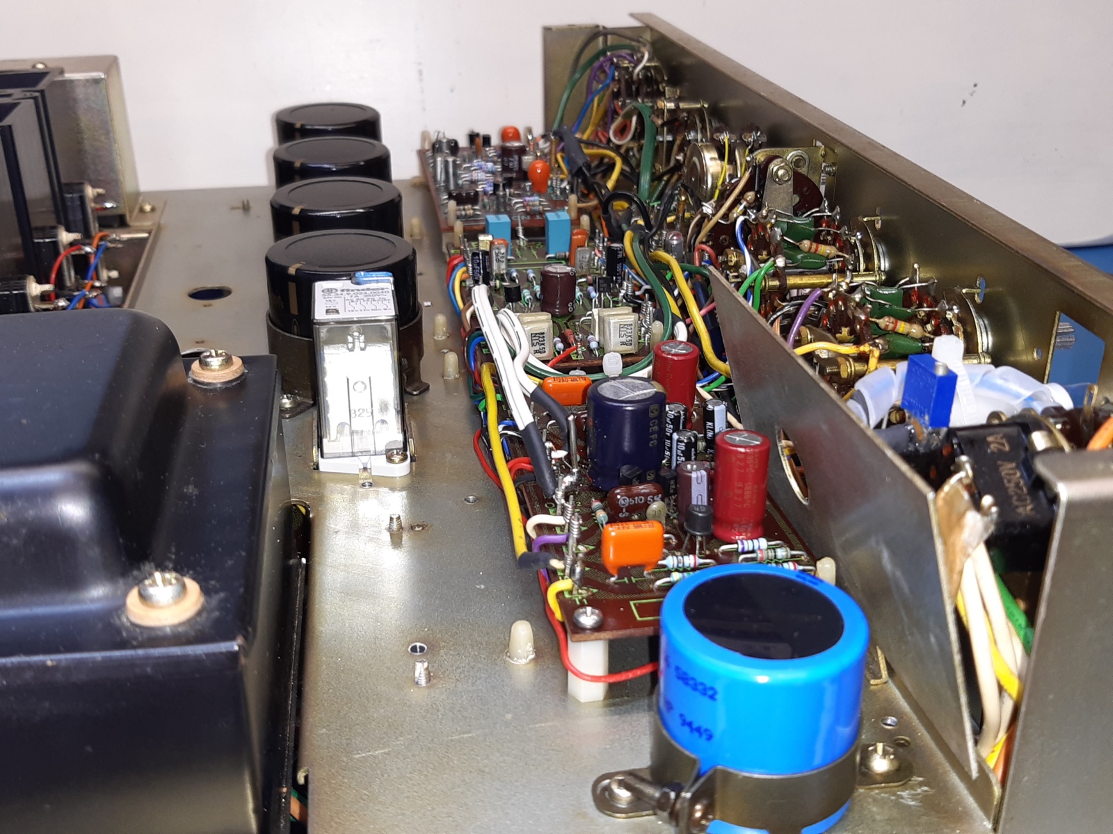
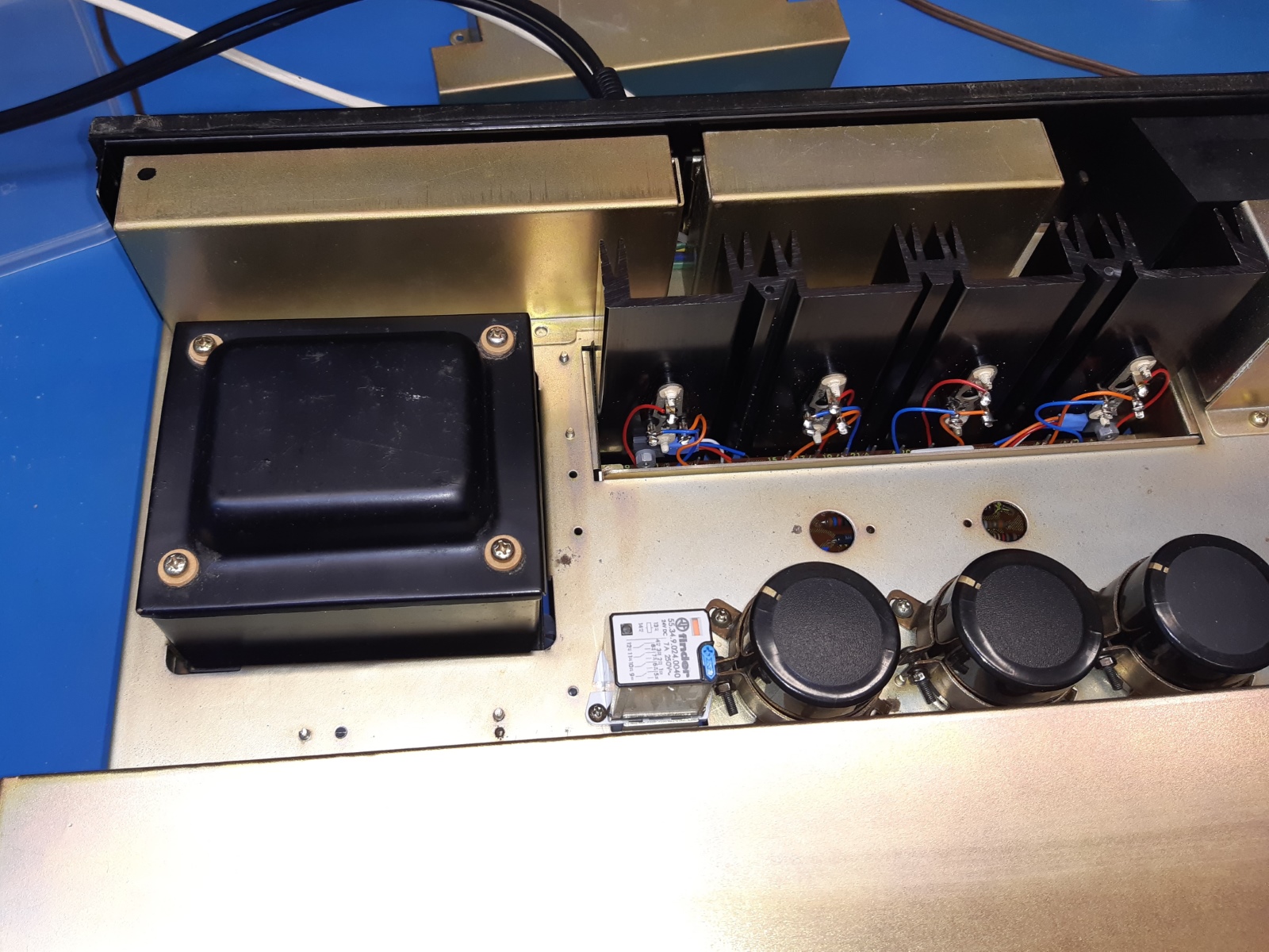
The new main amplifier DC power smoothing capacitors. On the right, also the new protection relay is visible, it is on a socket, now.
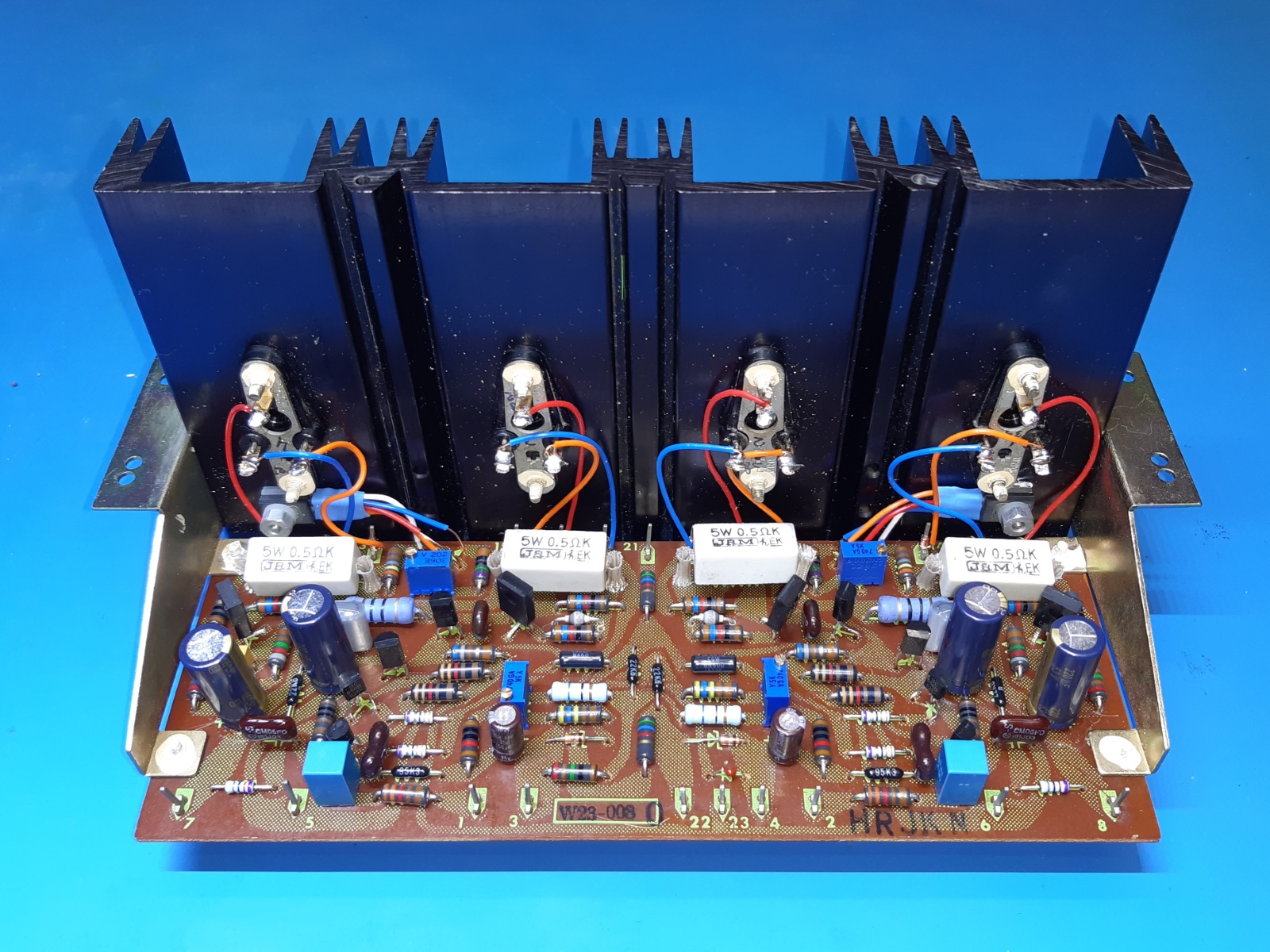
The pioneer sa1000 main amplifier, W23-008O.
The main amplifier appears still working. Look at the temperature pickup transistors which are mounted using tape to the heatsink.
Always suspect the "solid aluminium" Sanyo input capacitors.
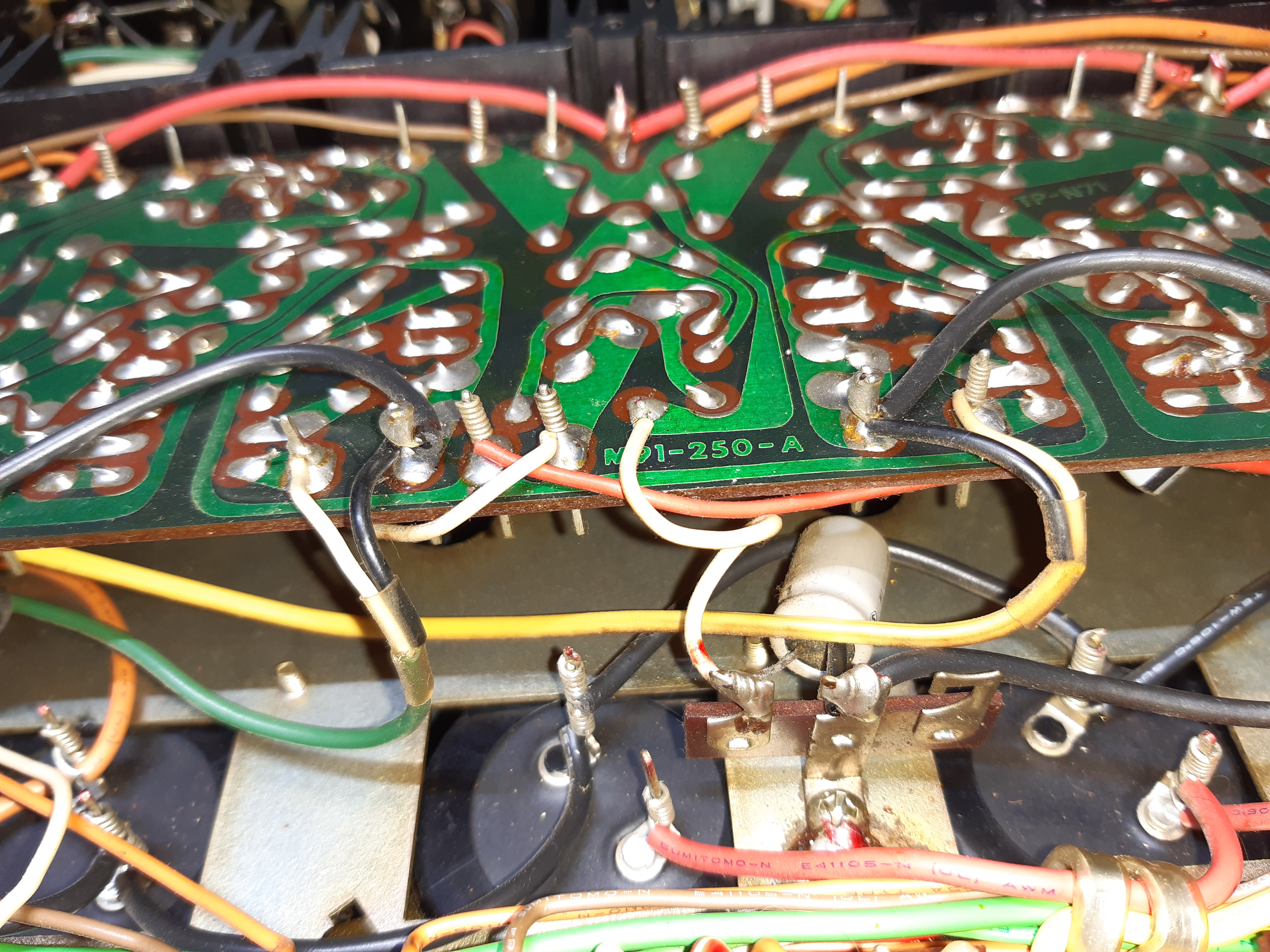
On the picture on the right, see the capacitor mounted from the ground to the minus 41 Volts. Probably the way the original wiring was routed was so long it created problems. I replaced the cap, but I do not know if it is still necessary, as I did reroute the minus 41V wiring from the big capacitors to the pcb making it a lot shorter.
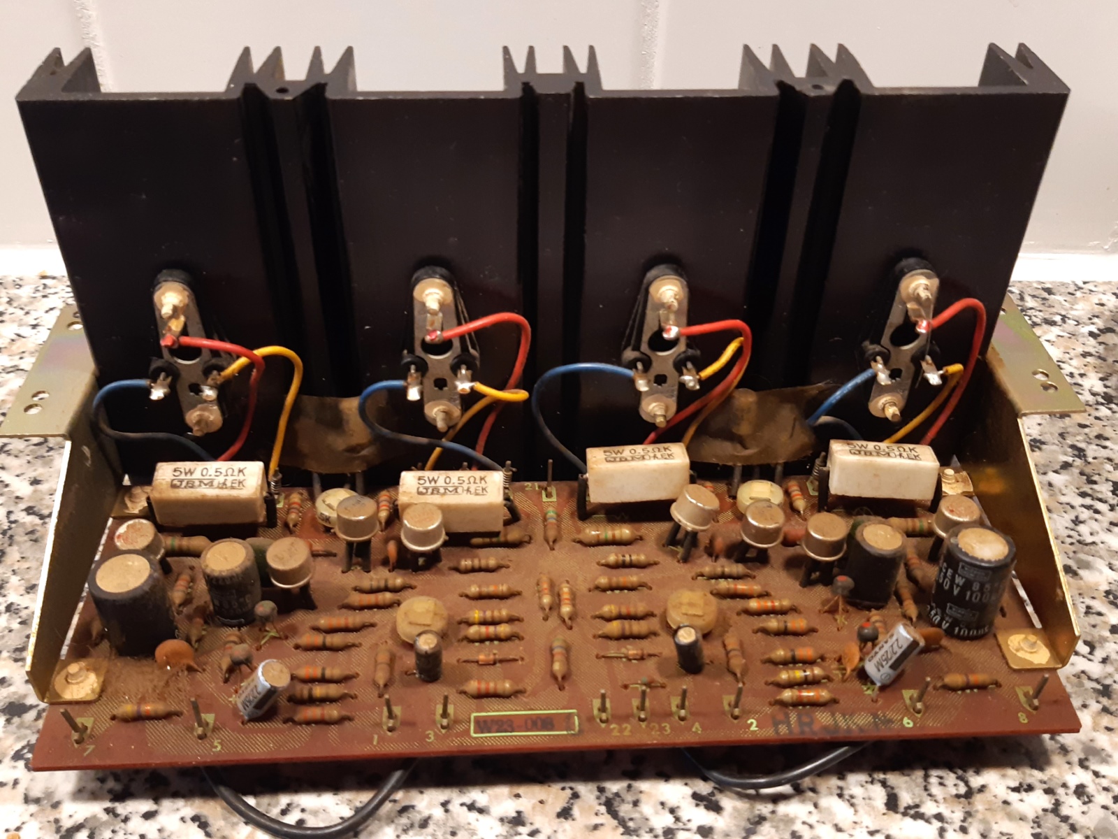
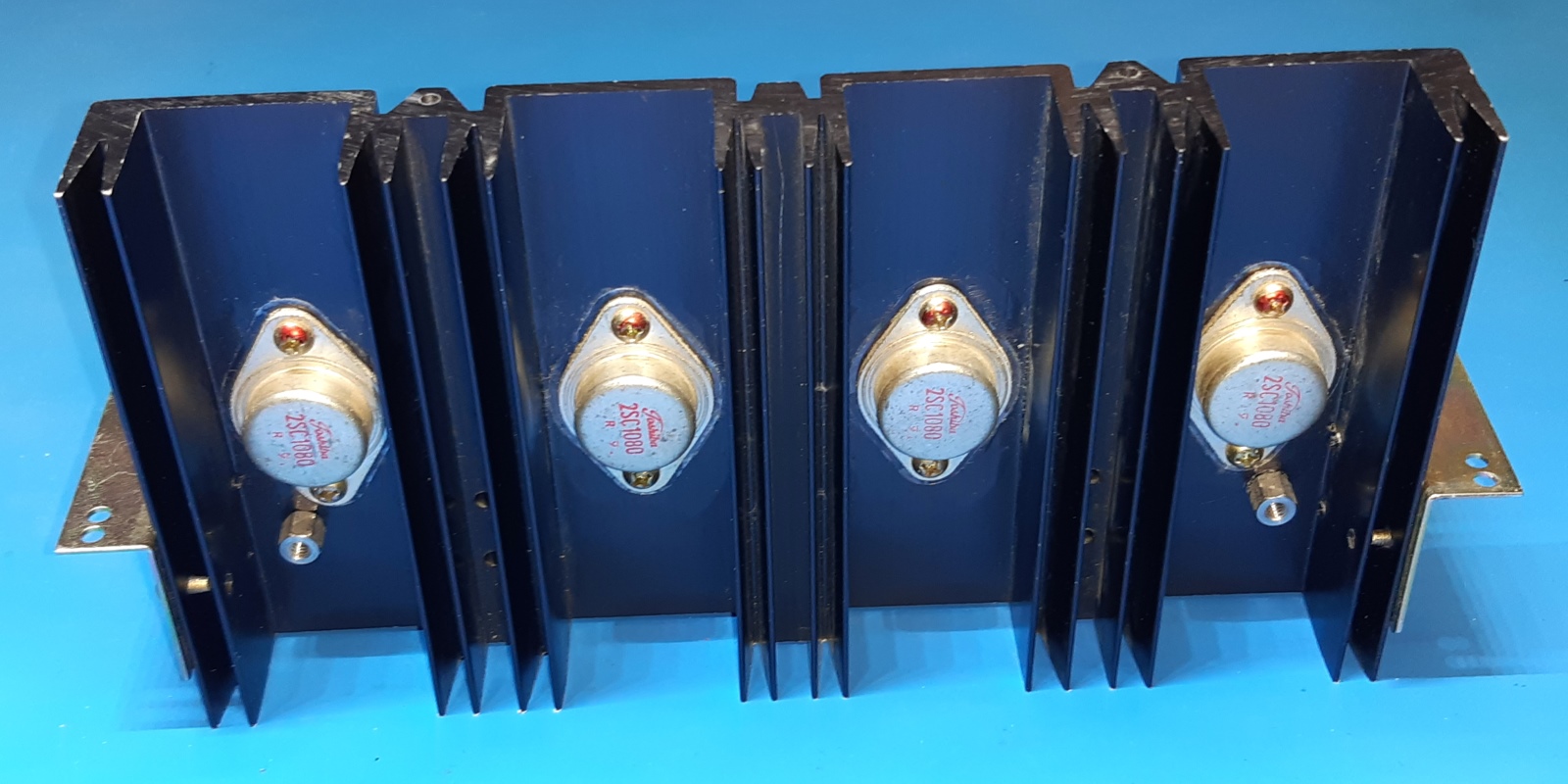
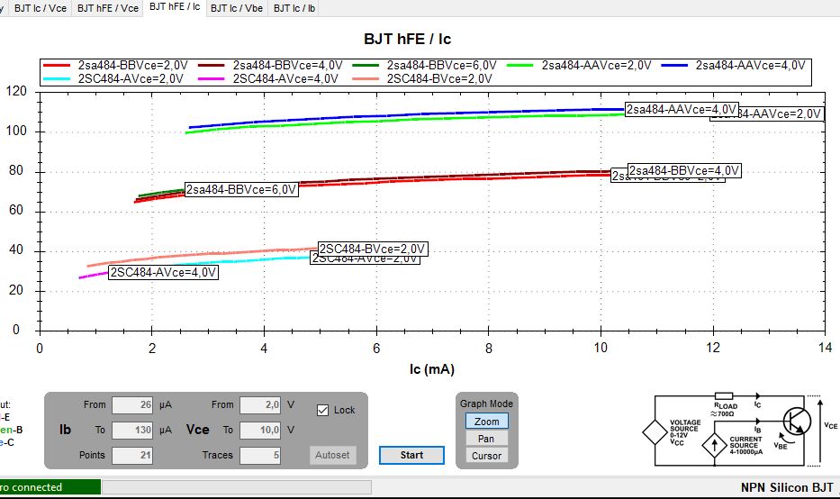
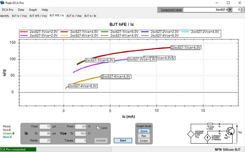
I retained the amplifier output transistors, after measuring the HFE. I presume HFE to be sufficient.
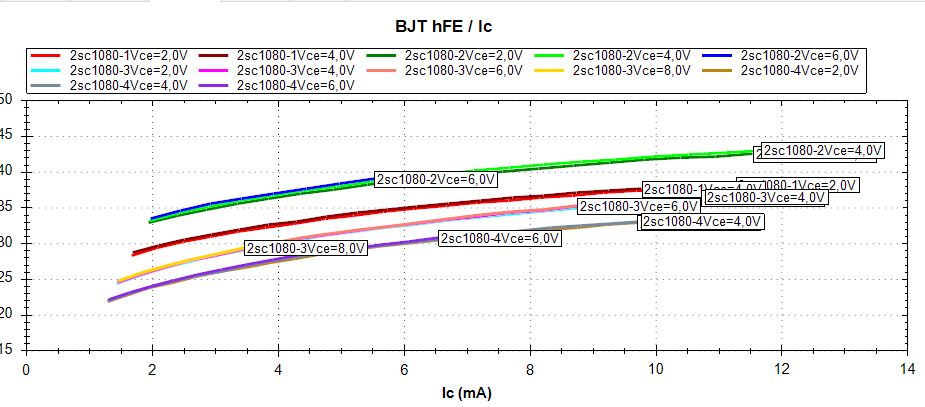
Part of the 2SC484 are considered somewhat low on HFE, as part of the 2SC627, so everything was replaced. KSA1220/KSC2690 for the drivers.
I mounted diodes and adapted the affected resistors R41 and R42 for a "baxandall diode modification" intended to lower distortion. The bias regulation gets new potentiometers and resistor adaption and BD329 transistors, which can be mounted using bolts.
D3 and D4, the SH-1S diodes, are replaced by BD136 transistors b-e junctions, physically attached to the BD329 transistors using crimp sleeve.
Most resistors are 0.5 watt Corning Glassworks metal film.
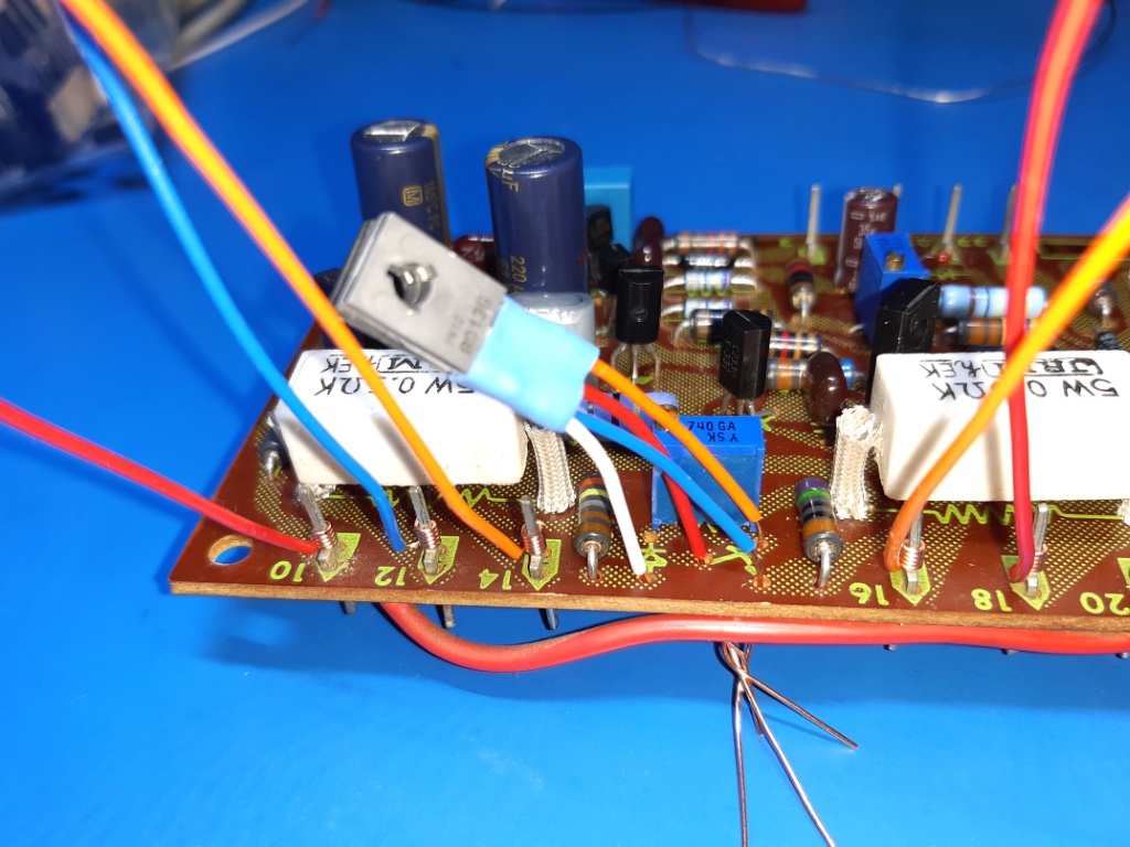
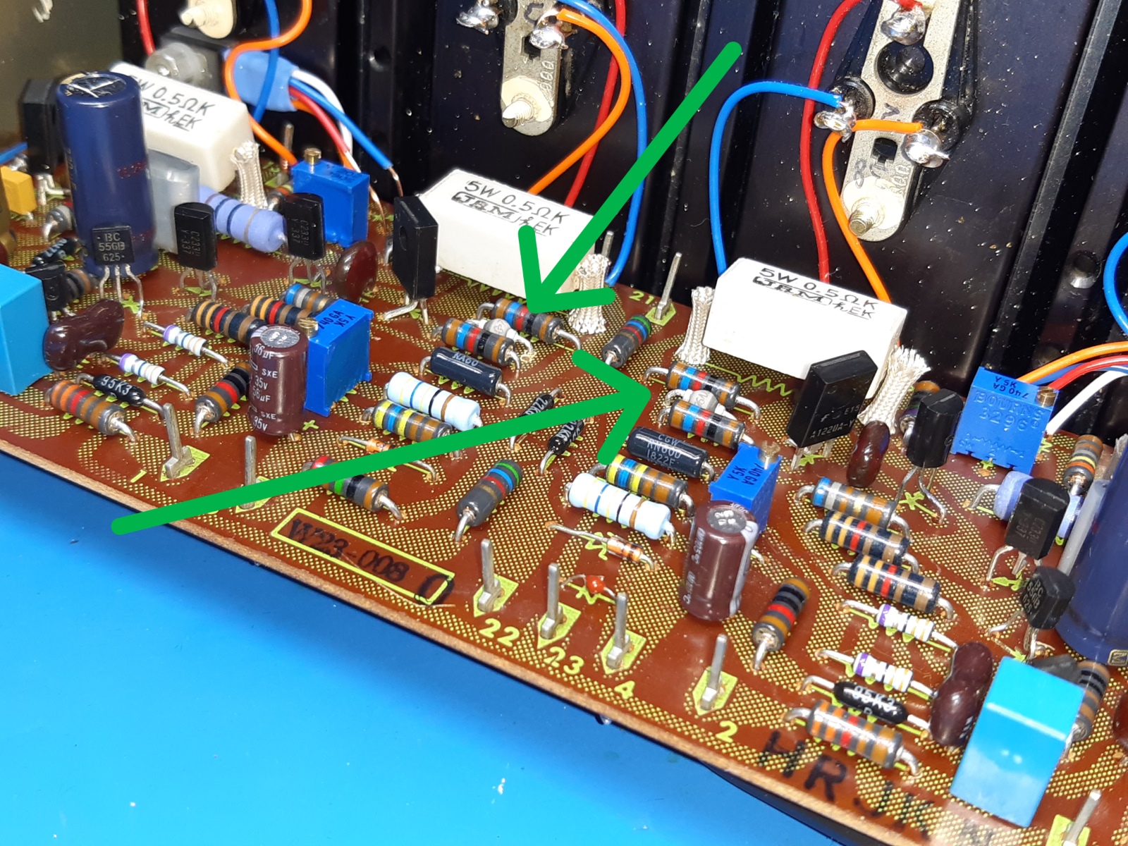
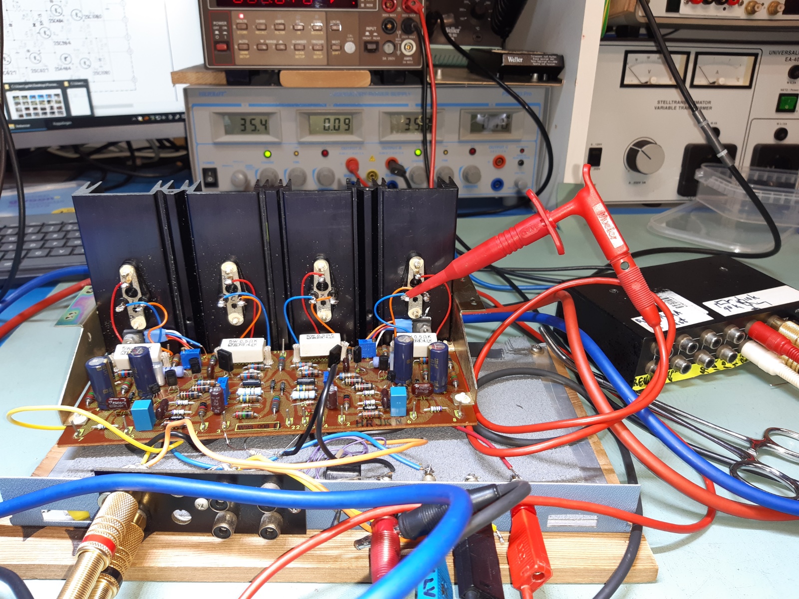
A picture of setting initial nulling and bias before mounting the amp unit back in the chassis.
The VAS transistors are KSC2330 now, and the input pairs a selected BC556B.
The Pioneer SA1000 head amp, W21-007.
The wiring at this amlifier is rather messy.
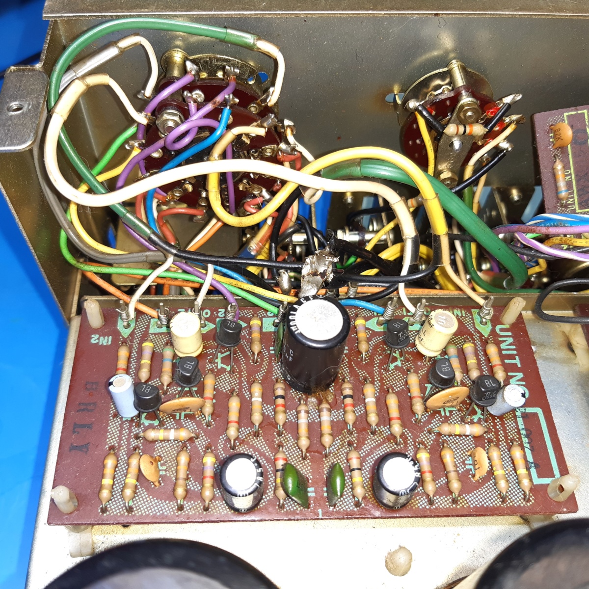
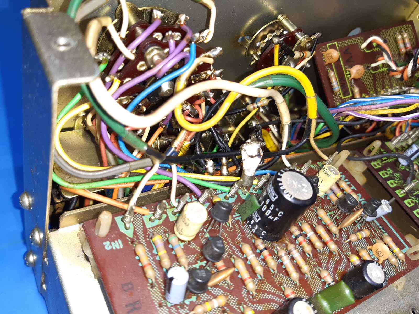
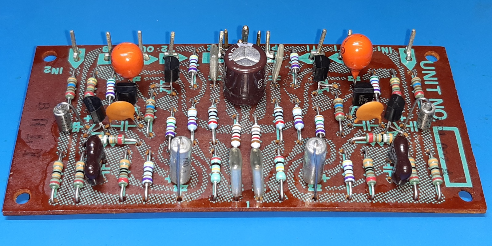
The new transistors are BC549C. Apart from the power smoothing electrolytic cap, the others are good quality type tantalum ones.
The resistors I use are mostly 1% tolerance metal film ones for low noise, some are 5% or 0.1% tolerance.
The pioneer sa1000 filter unit, W28-004.
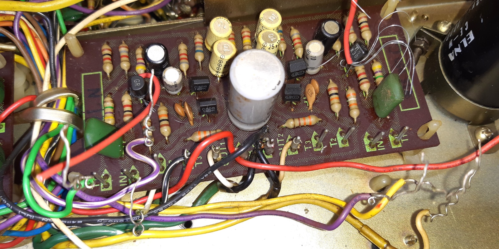
The filter unit circuit card itself is partly not populated, I needed the schematic from one manual and the layout from another to cobble together the actual situation.
Observe the big green capacitors, they show cracks on the top.
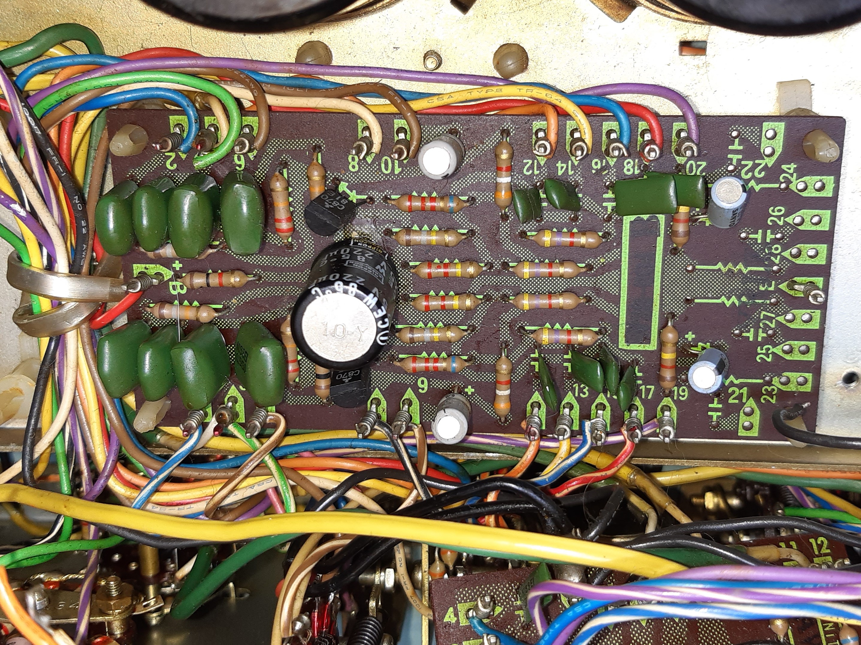

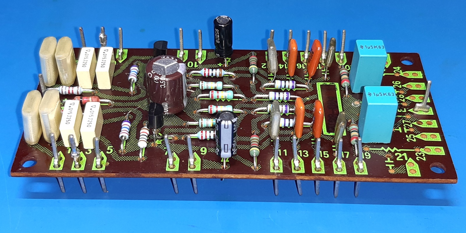
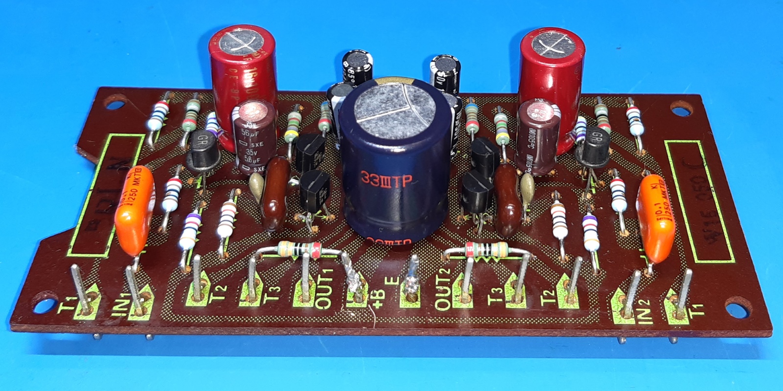
The pioneer sa1000 control amp,W15-050C.
If wanting to retain the field effect transistors, make sure to protect it against static during disassembly of the card! Before tinkering the card, I wrapped pieces of wire around the jFET legs.
Also this card did get new parts.
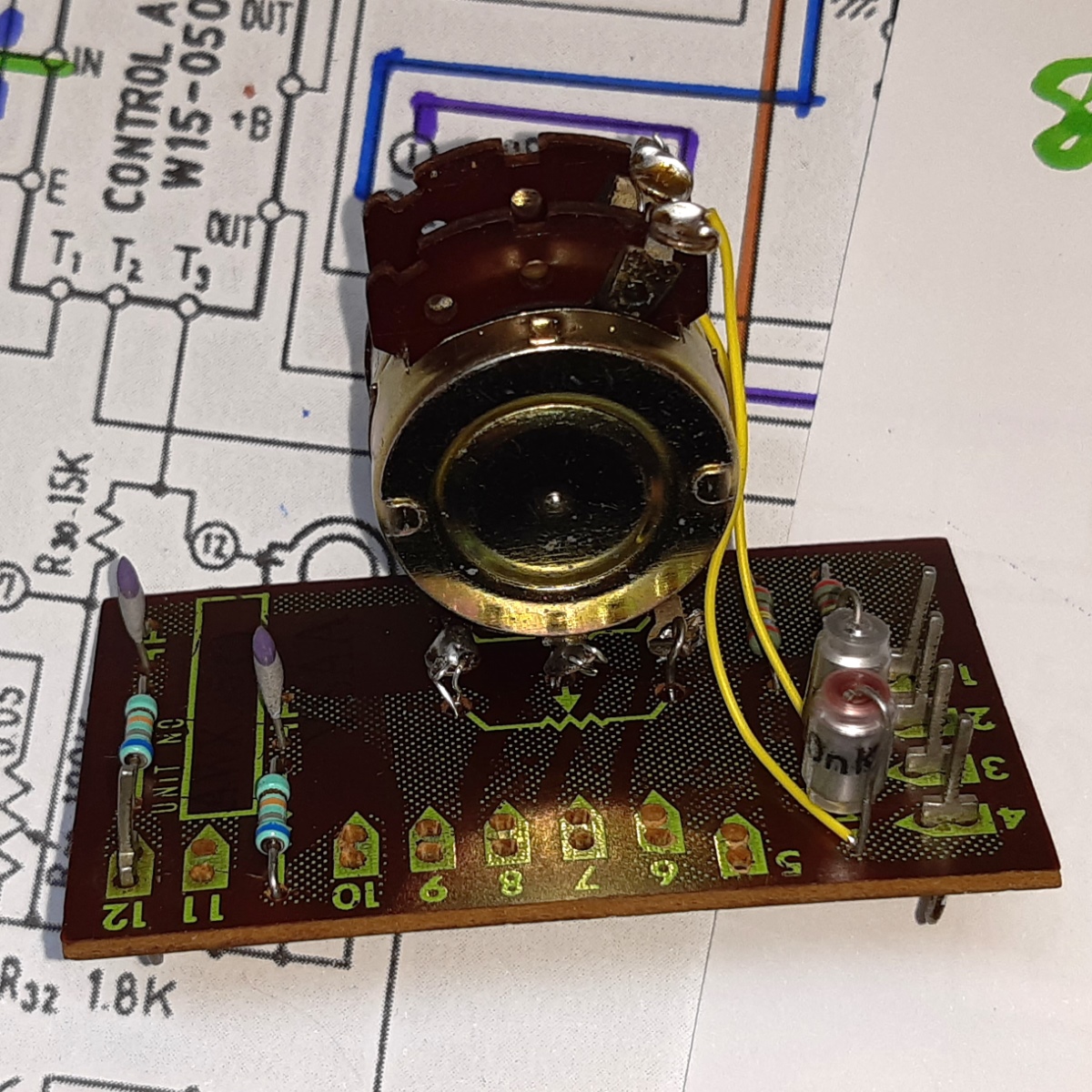
The pioneer sa1000 volume unit, AWX015.
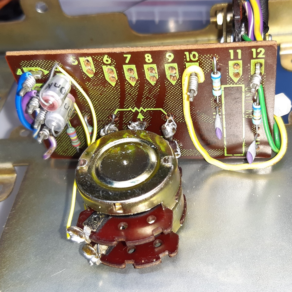
The volume potentiometer appeared to be replaced, having its circuit card AWX015 loose in the unit.
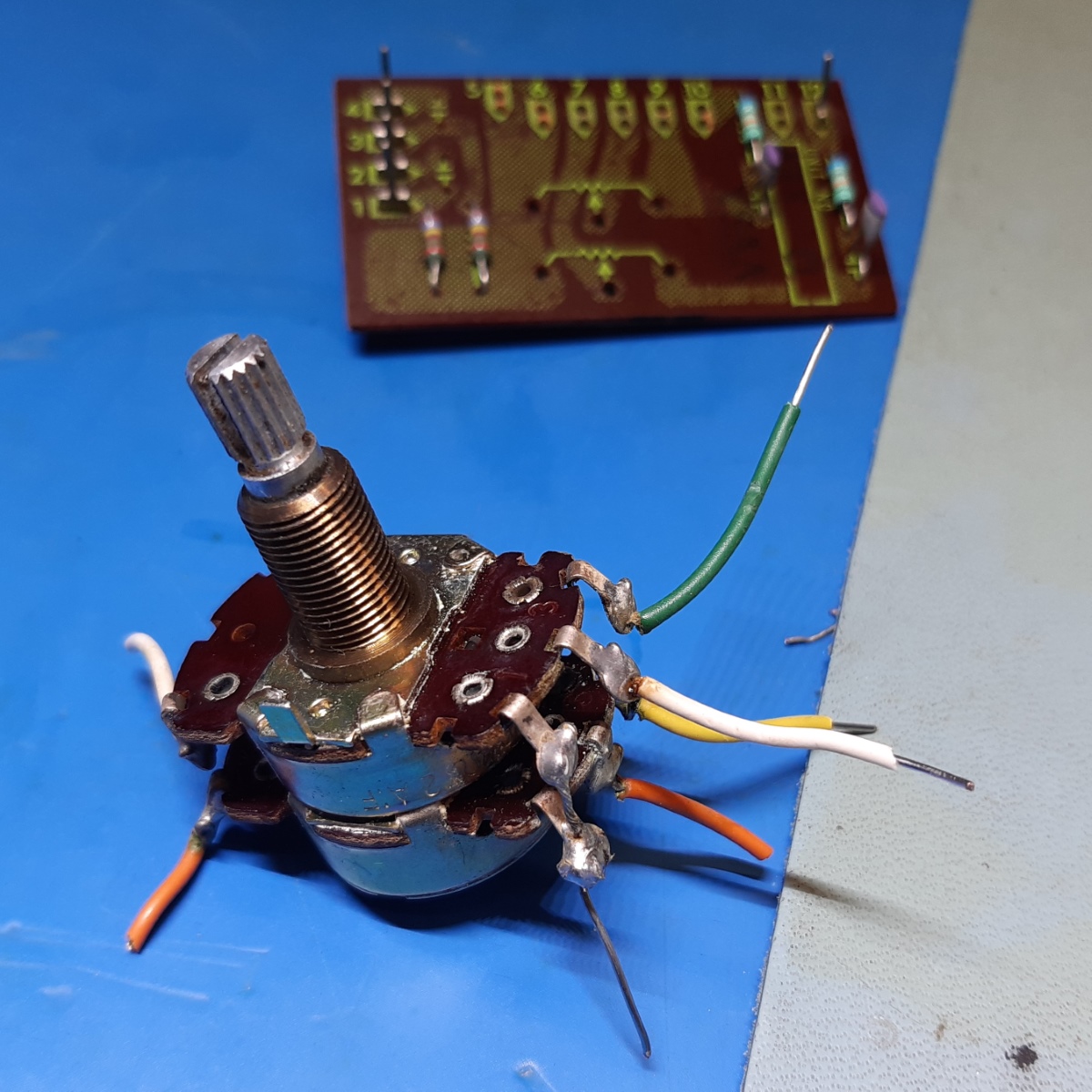
The otherwise nice square Alps potentiometer appeared not suitable at all for its resistance, and it was wired up totally wrong, too!
I hoped to find an alike replacement in my scavenged SA800 or SA600 units, but no luck. Fortunately, I had a more or less suitable replacement, which I could use adapting its mounting using wires.
The big arrows show the original (wrong) potentiometer and on the right is the volume circuit card. (the small one shows the old protection relay)

In the end, the card can be mounted, again.
The pioneer sa1000 protector unit, W28-008A.
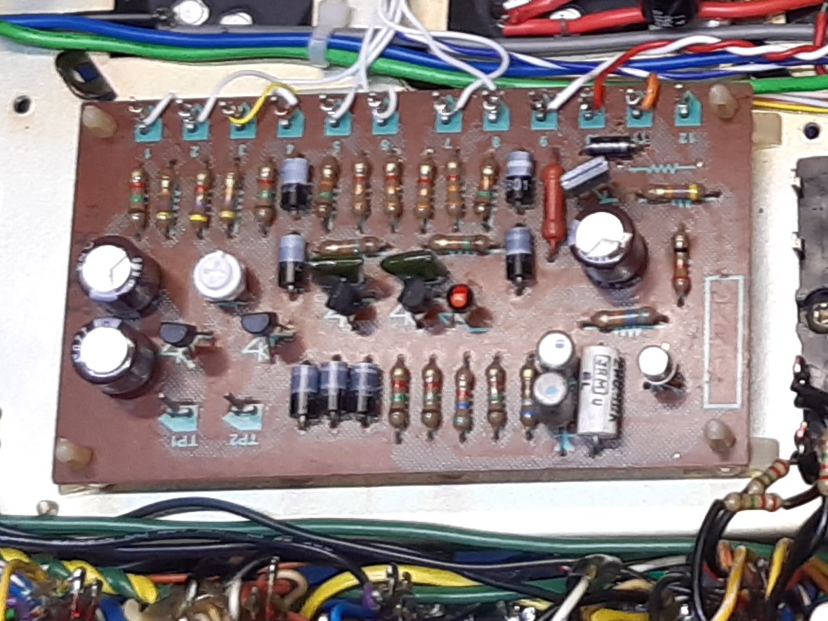
The protection card has two special TO-1 devices and would need redesign if taken out, as those semiconductors are obsolete. I decided to not totally refurb, on one of the pictures you see the card missing the parts I DID replaces, the others are as it ever was. The special devices seem dropping around 1 Volts, so they could be some type of dual diode.
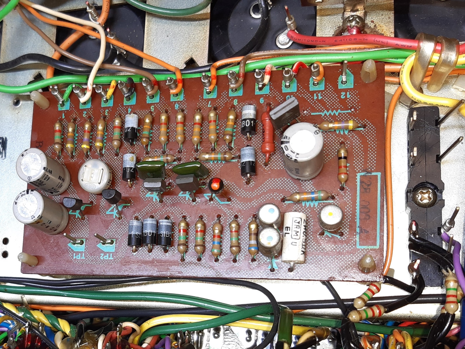
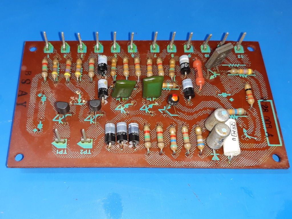
I added a transistor protection flyback diode on the upper right side of the protection card.
The front and sides of the amplifier.
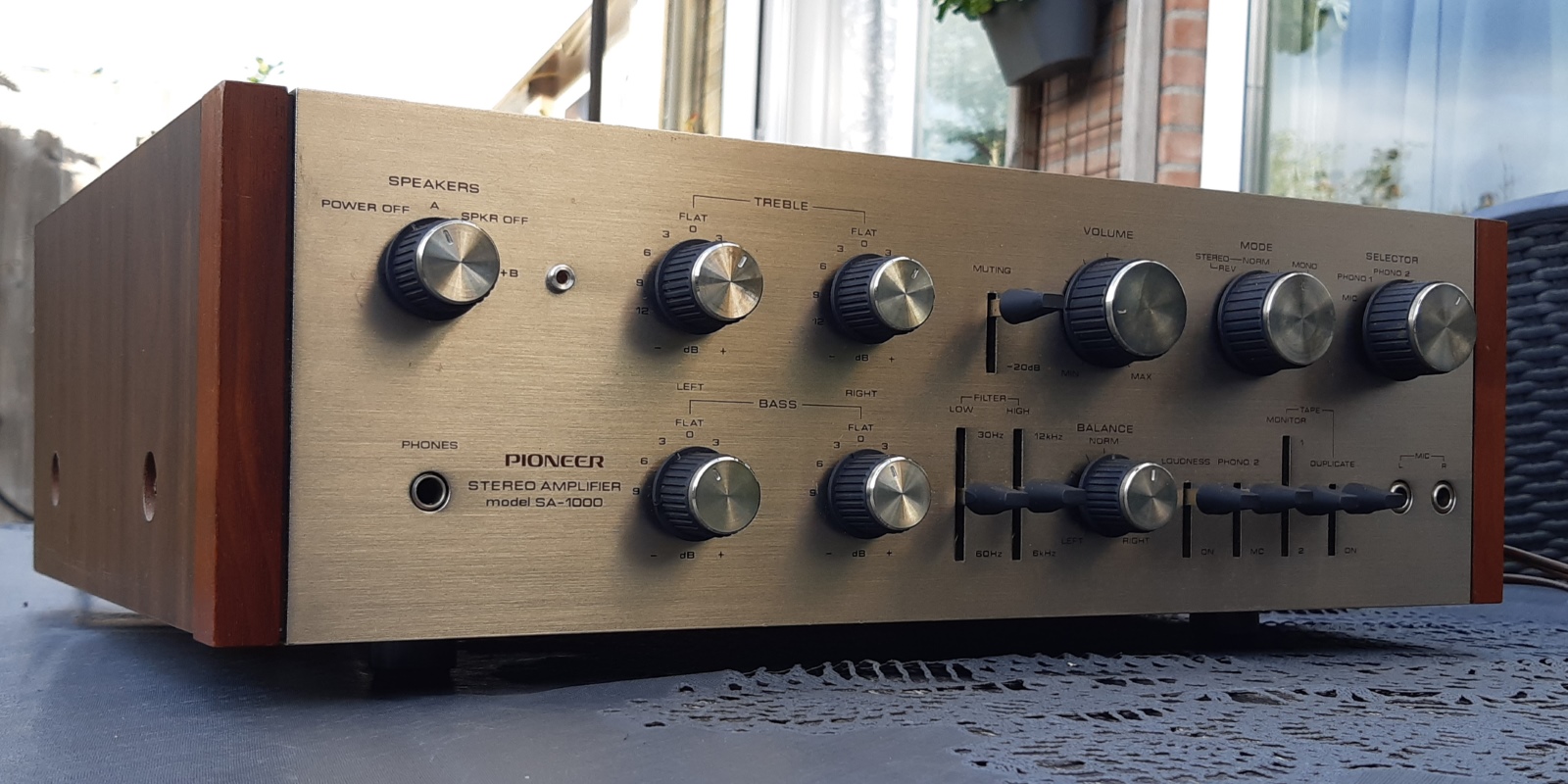
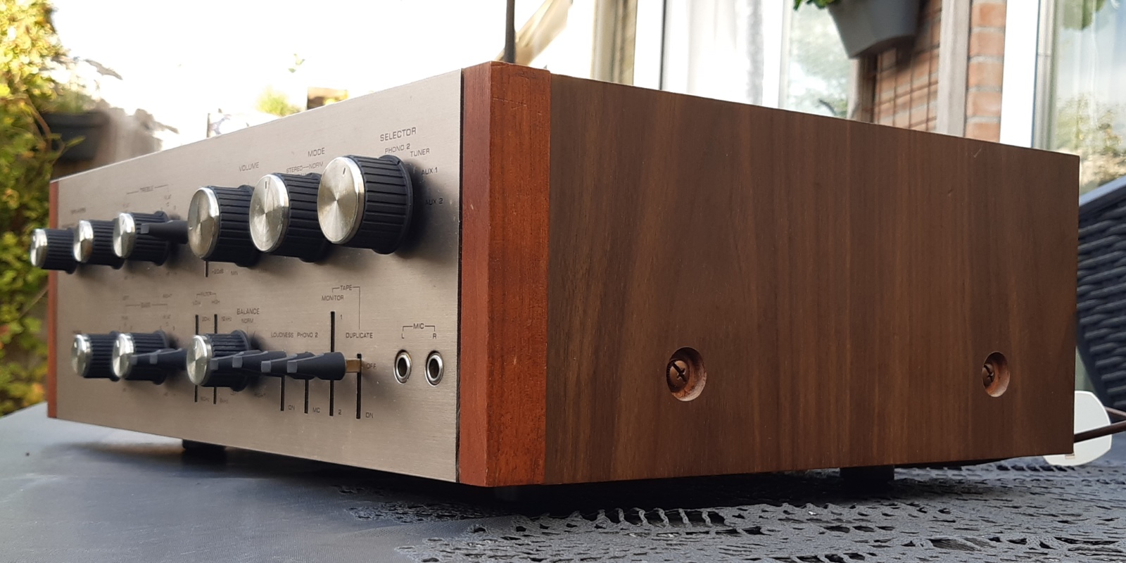
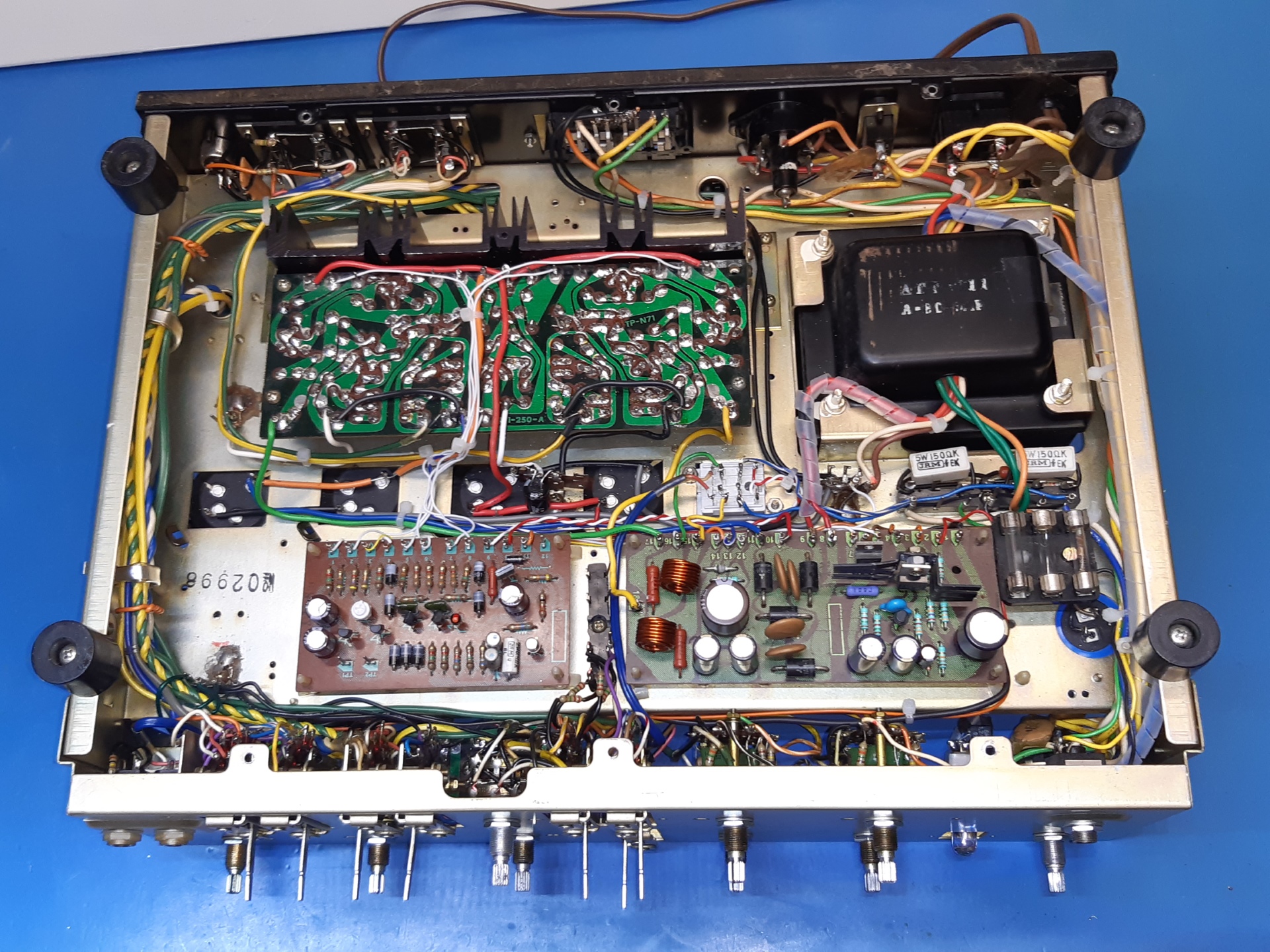
The bottom of the amplifier.
The top of the amplifier.
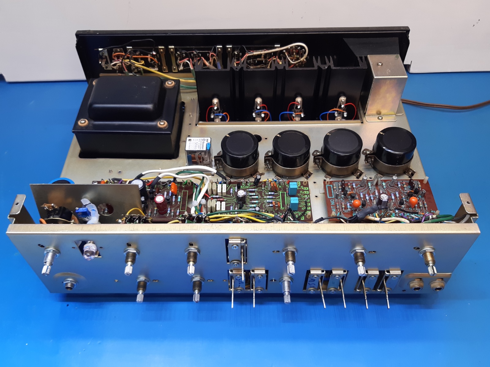
The blue capacitor is the main smoothing capacitor for the preamp section.
Now, including the shields mounted, the two on the back come from a scavenged unit.
Ga naar Gerards homepage / go to Gerards main page ---->>>