Ga naar Gerards page / go to Gerards other page ---->>> ![]()

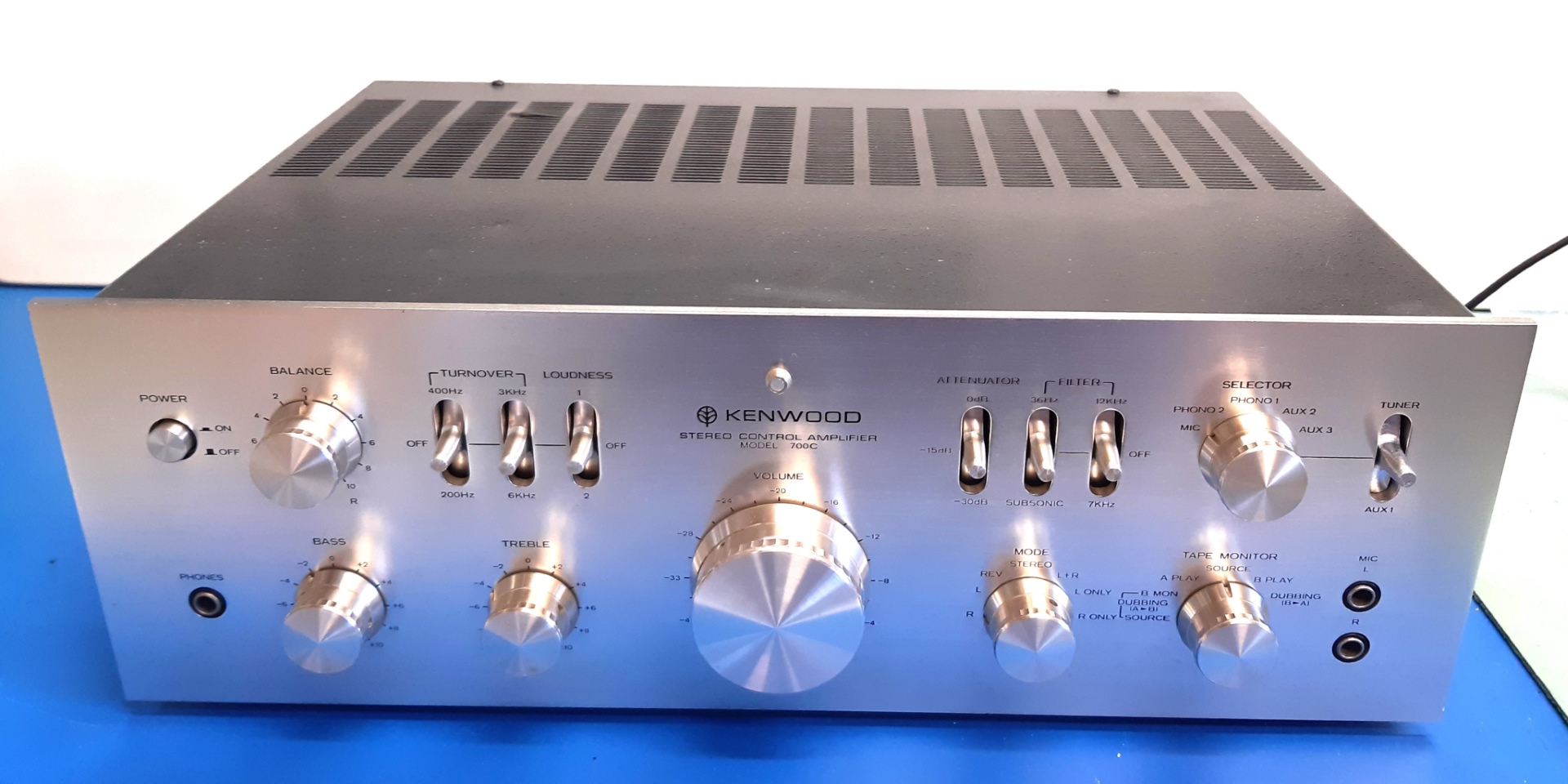
Kenwood 700c recap / revisie / refurbishment, 2014, revisit 2024
Gemakshalve is deze pagina in het Engels geschreven.
![]() This page is written using English language only.
This page is written using English language only.
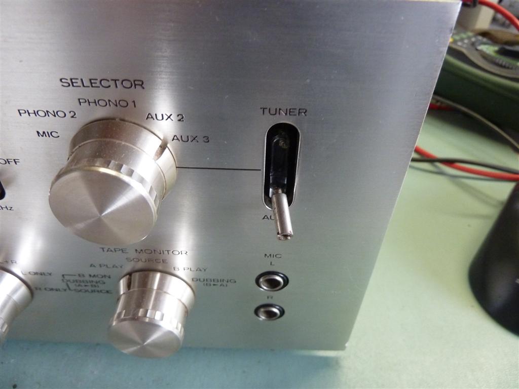
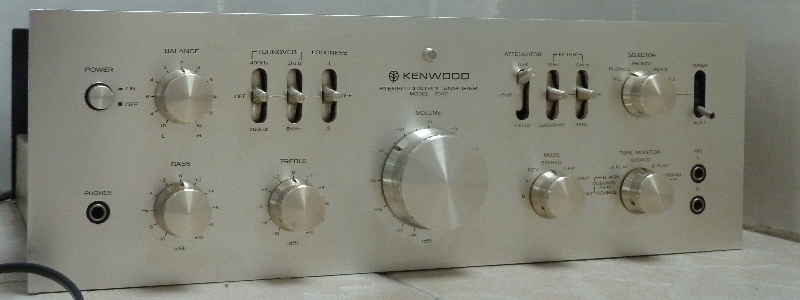
This Kenwood Supreme Series 700c was bought having one missing toggle lever and one loose lever cap. It did have serious distortion on both channels. It was "worked on", before. The back is pushed in at a corner a bit. Further, it looks in pretty good shape.
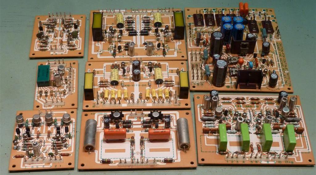
It is a well regarded pre-amp from the seventies. When taking it apart, it is quite obvious it is of a neat mechanical design. All electronic functions have their own circuit boards. The layout of the boards is roomy, enabling service.
Although not necessary, and instead of only fixing what was wrong first, I decided to update it as a journey to gain experience how this all connects together, as I did not have a service manual (now, in 2024, I have).
The schematic is available from different sources, like on Hifiengine and, without need of an account, on Elektrotanya.
I took advantage of the circuit boards being ready for bigger non-electrolytic capacitors. Apparently, Kenwood decided some film capacitors to be too expensive, using aluminium electrolytics instead.. They did put extra tracks and holes on the pcb's, and they added text, to cater for upgrade. This is why on my pictures, sometimes component relocations can be seen.
The following was done:
Replace old electrolytic capacitors (recap, although the need for this is always arguable),
Replace almost all transistors, especially the types supposed to fail over time (2SC1451)
Replace burnt resistors (from some the paint was burnt off) and composite carbon resistors as they get unstable over time, as most carbon film ones were replaced by metal film ones, anyway.
Clean boards and parts. Some components may be replaced just because of availability and cleanliness (looks).
Raise the power voltages for the headphone amplifier, as they are below the specified + / - 5 volts, making the amp performance more satisfactory using headphones having over 8 ohms impedance.

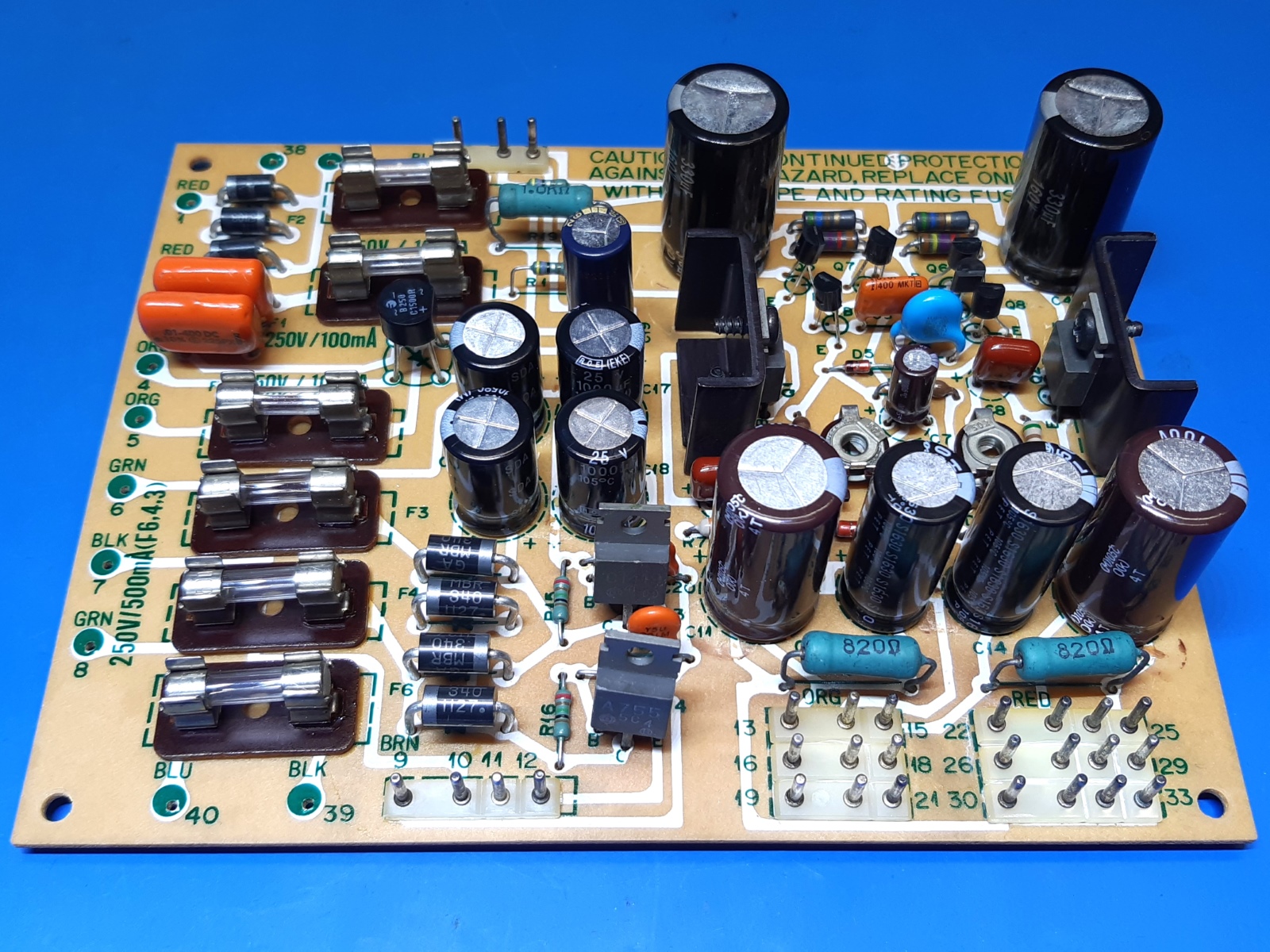
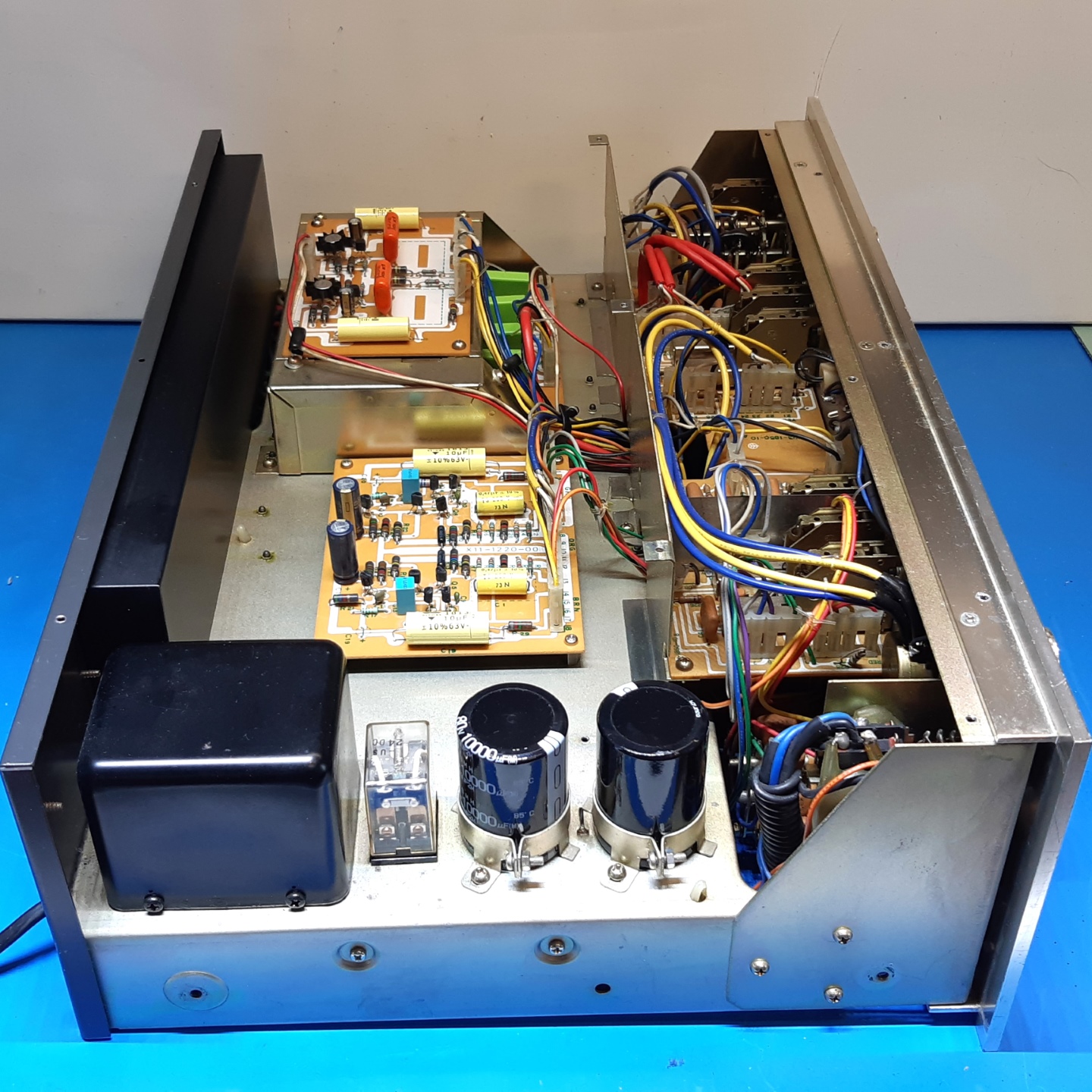
The Power supply block (X00-1470-10)
The power supply block supplies several voltages:
+ and - 50 volts adjustable, electronically stabilized, for buffer amp and equalizer amp
+ and - 24 volts, derived from the 50 volts and zenered to 24 volts, for mike amp, low filter board, tone amp.
+ and - 5 volts, stabilized by transistors, for the headphone amp.
+ 24 volts unregulated, for the relay board
AC 7.5 volts, for the power lamp.
The input of the 50 volts supplies is coming from smoothing capacitors of 2200uF rating.
To cater for new smoothing capacitors, I opted for 1N5408 diodes specified for 3 Amps versus the 1.2 Amps ones, migitating inrush current risk.
The input voltage appears to be almost 60VDC, having a little less than 100mV ripple on the capacitors.
I exchanged the 2200uF capacitors for 10000uF ones, the ripple is below 50 millivolts, now.
C3 and C4 are 330uF/160V now, although overkill, they do fit the circuit card nicely.
The zener diode bypass capacitor is 56 microfarads, which should make zener noise somewhat lower.
The plus and minus 24 Volts lines appear to be almost + and - 25 volts.
The DC voltages for the headset amplifier appeared 8.5 volts preceding the regulator transistors, and 4.5 volts regulated was left.
To have a little out more voltage possible for headphones having higher than 8 ohms impedance, R15,16,17,18 have been changed, to get more voltage out of the power supply. It also appeared to have lowered the DC offset on the headphone amplifier from 70 to 30 millivolts initially.
Revisiting the amplifier in 2024, I decided to change the rectifiers to Schottky MBR340 ones, to squeeze the very last Volt out of it. The smoothing caps are 1000 microfarads, instead of originally 470. I have + and - 6.2 Volts available, now!
Replaced parts:
| Q5,7,9 KSP42 | Q6,8,10 KSC992 | D9,10,11,12 MBR340 | D1,2,3,4 1N5408 |
| C1,2 10nF 400V Sprague 225px | C3,4 333uF160V Pana ED | C5 10nF MKT Philips | C7 56uF 35V Nippon Chemicon. |
| C8,9 470nF film Panasonic | C11,12 470 uF 100V Nippon KME | C13,14 560 uF 63V Ruby ZLH | 19, 220uF 63V Panasonic FC |
| C15,16,17,18 1000uF 25 V Roederstein EKE | C20,25 1nF 1kV Y5U | ||
| R1,2 4.7 ohm 1 watt inflammable | R15,16 330 ohms -> 215 ohms | R17,18 560 ohms -> 825 ohms |
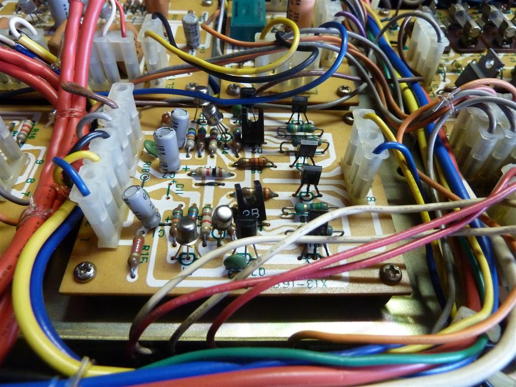
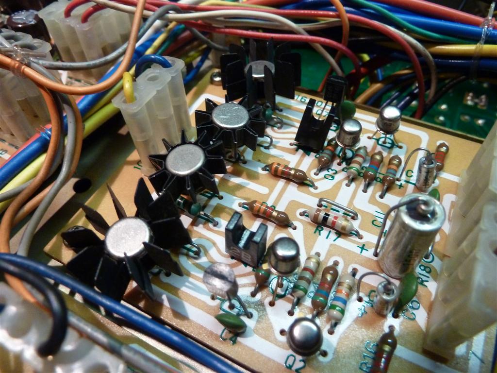
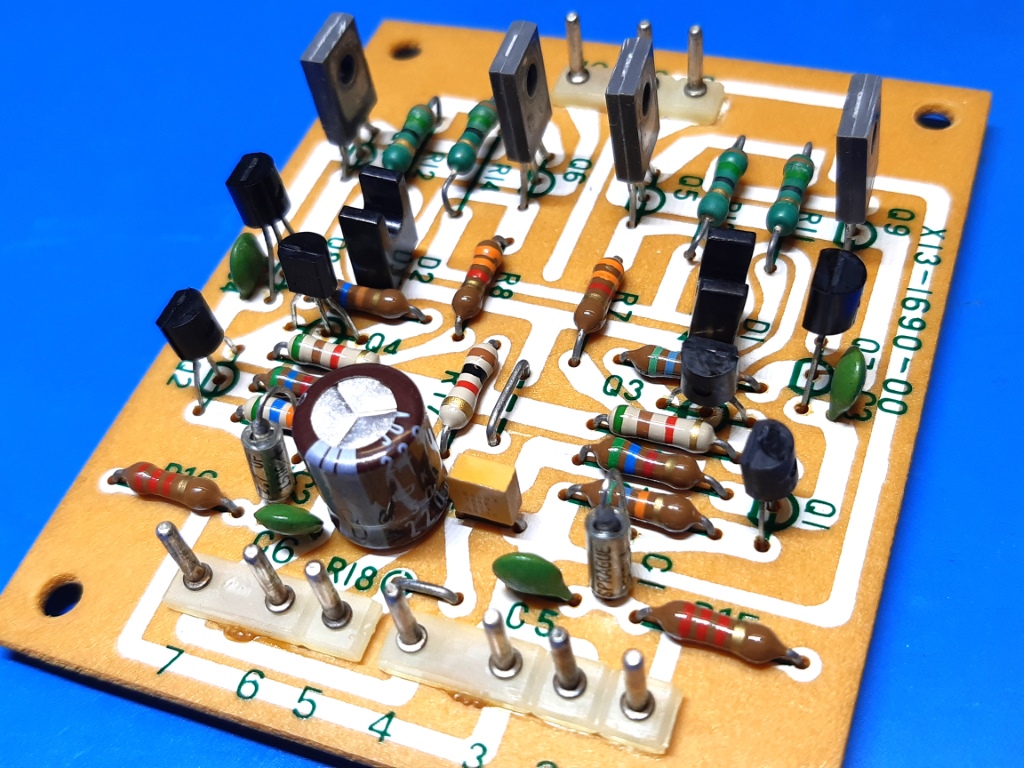
Headphone amp (X13-1690-00
The headphone amp is a low power (20 milliwatt) single ended class A amplifier designed for 8 ohms headphones.
It takes the pre-amp outputs (from the Low filter block) as the source, it has an additional volume control on the back of the chassis.
It was found having the small plastic output transistors 2SC1213A and the current source transistors 2SA673A all having black corroded pins. One 2SA673 HFE was only 14, so it was defective. Note, they run hot and these were small plastic ones, which might have contributed to the failure of one.
They were replaced by BC160 and BC140 initially. The DC offset voltage appeared to be around 70 millivolts at no load.
When raising the power voltage to + / - 5.7 volts, it went down to 20 mV on one channel and 30 on the other. After replacing Q1,2,3,4 it went to 21 millivolts at both channels.
Because the amp did not have enough headroom to have a reasonable volume at higher impedance headphones, this power was raised from the measured 4.5 volts to 5.7 volts, the maximum I could get.
2024 change:
Replacing the rectifier diodes in the power supply by MBR340 Schottky ones, did get me another 0.5 Volts, so in the end the voltage is + and - 6.2 Volts.
I still have to test for perceived volume at higher levels.
The initial picture show the 4 small transistors not replaced, yet.
There is no HF bypass, C11 location was available and I decided to call the one on the other power rail I mounted below the pcb C10, I did put 100nF there.
For neatness reasons, I decided to put in TO-126 type transistors as output current source (BD136) and amplifier (BD329).
Replaced parts:
| Q1,2,3,4 KSA992 | Q7,8 KSC945 | Q9,10 BD329 | Q5,6 BD136 |
| C1,2 1 uF 50V -> 2.7uF 15V metal tantalum Sprague 150D | C7 47uF 6.3V ->220uF 50V Nippon Chemicon KMG | C10,11(!!!) 100nF CK05BX ceramic |
2024 situation:
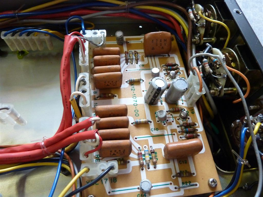
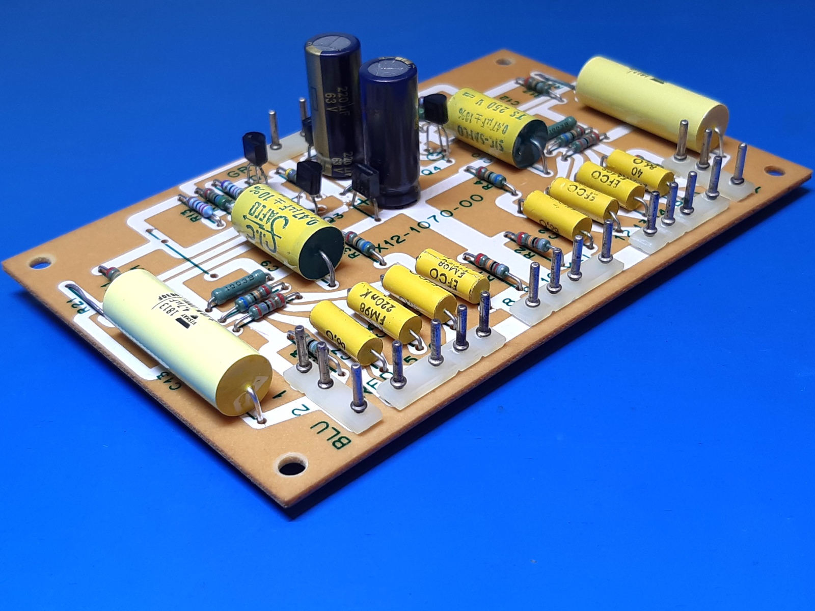
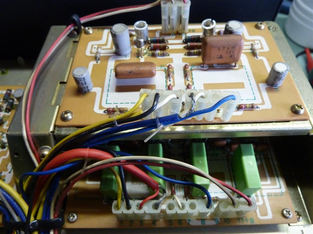
Low filter block (X12-1070-00)
The low filter block is actually the output amplifier. It has filter circuitry also, which is bypassed when not in use.
I did put in film capacitors instead of the 3.3 uF bipolar electrolytic signal output ones. Other film caps were exchanged, just because nice ones were available.
The card already has locations/holes to cater for power line RF bypass capacitors, I used 8.2nF capacitors I had on hand. They are located next to the electrolytic ones.
All resistors are replaced by metal film ones, mostly SFR25 type.
Replaced parts:
| Q1,2 KSA992 | Q3,4 BC550C | two 100uF 35V caps by 220uF 63V Panasonic FC | two 8.2nF CK05BX as RF power supply bypass |
| two 470nF film caps by 470nF Sic/Safco axial | eight 220nF film caps by 220nF EFCO axial | Output 3.3uF Bipolars by 4.7uF Vishay 1813 axial. |
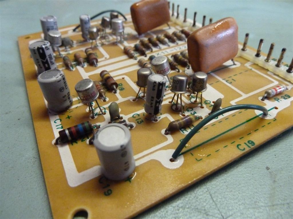
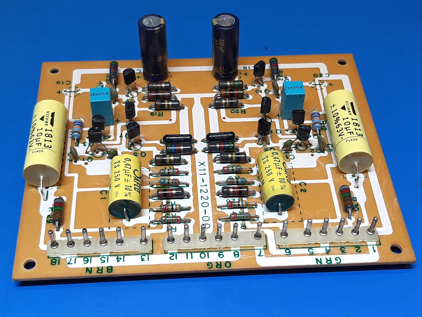
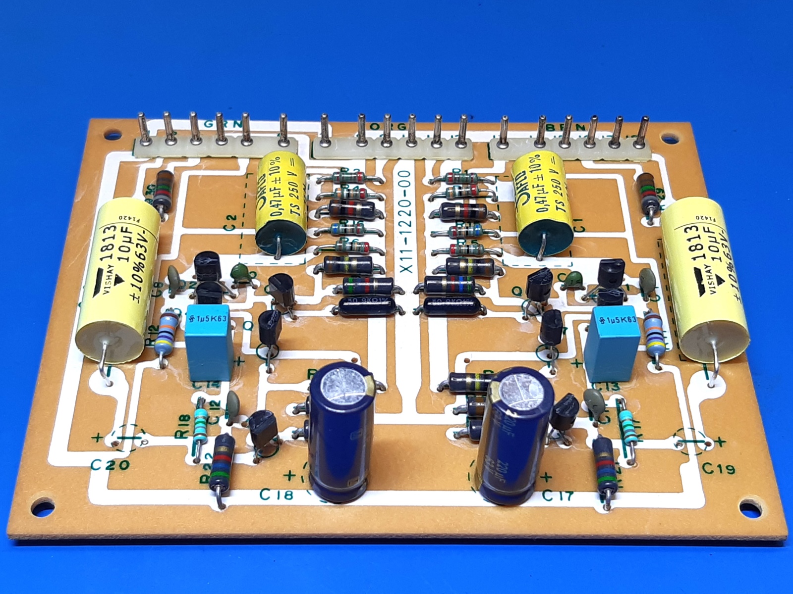
Tone amplifier block (X11-1220-00)
The tone amp block is in between the buffer amp and the filters+amp.
It appeared to have a faulty 2SA620 transistor, leading to audible distortion and a negative voltage on C14. The picture on the right still shows the original metal case PNP transistors.
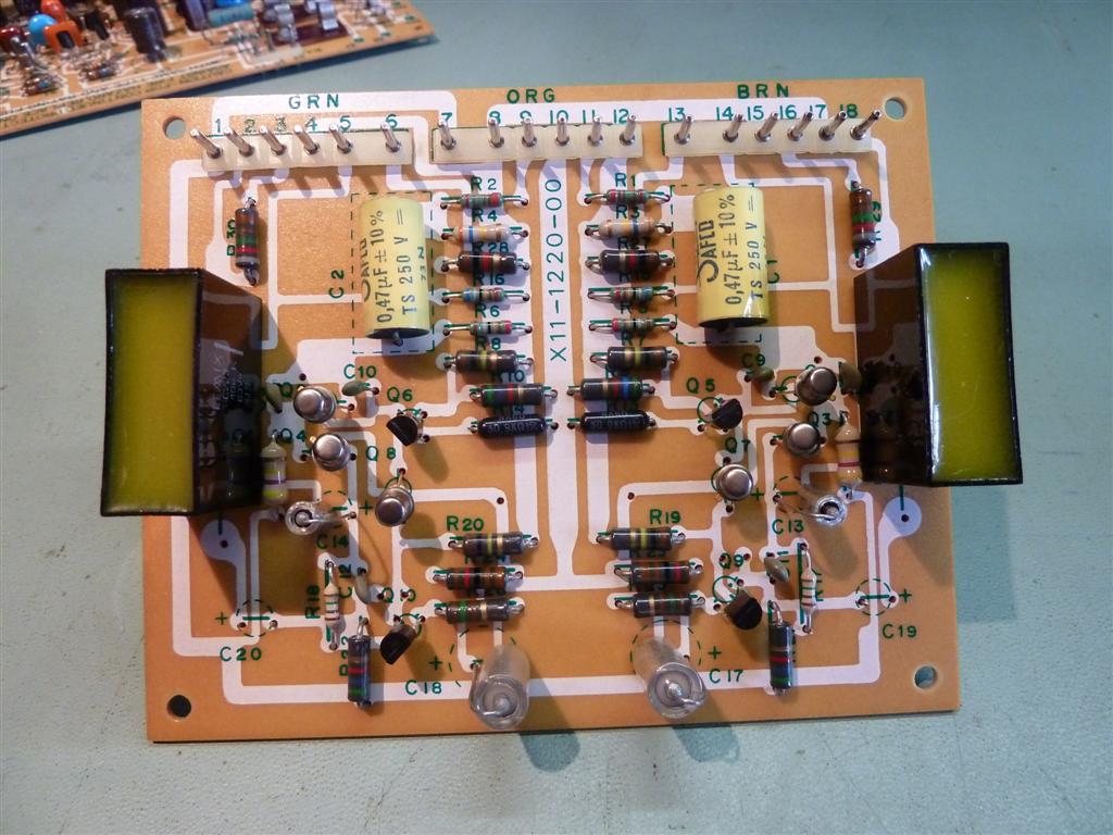
Replaced parts:
| NPN transistors by BC550-C | C1,2 0.47 uF Sic/Safco | C13,14 1uF 50V by 1.5uF 35V Siemens MKT | all resistors metal film |
| PNP transistors by KSA992 | C19,20 Bipolar 10uF 25V by 10uF 63V Vishay 1813 | C17,18 100uF 6,3V by 220uF 63V Panasonic FC |
2024 situation:
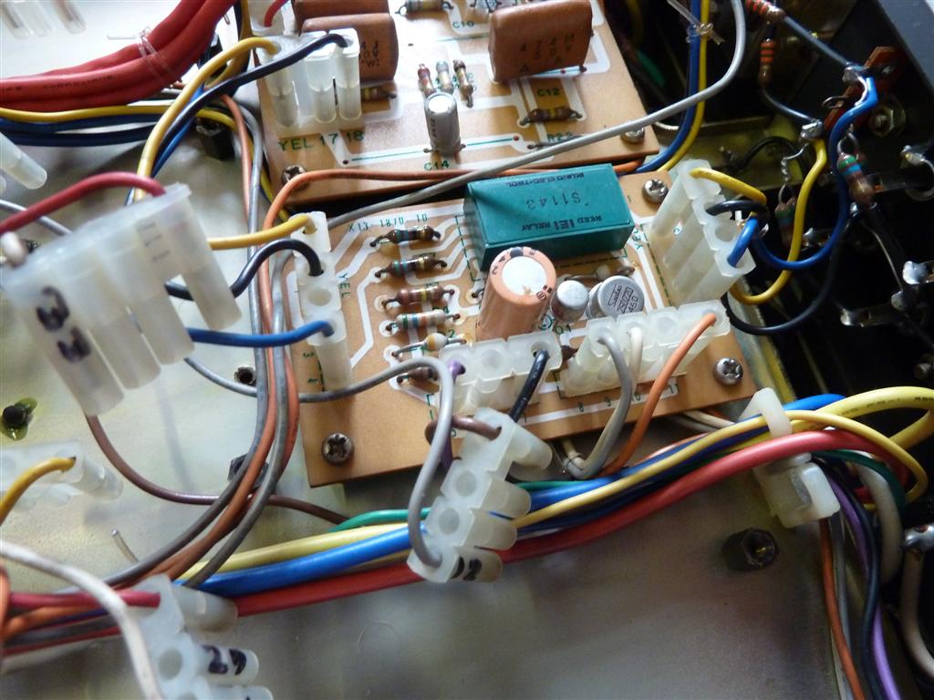
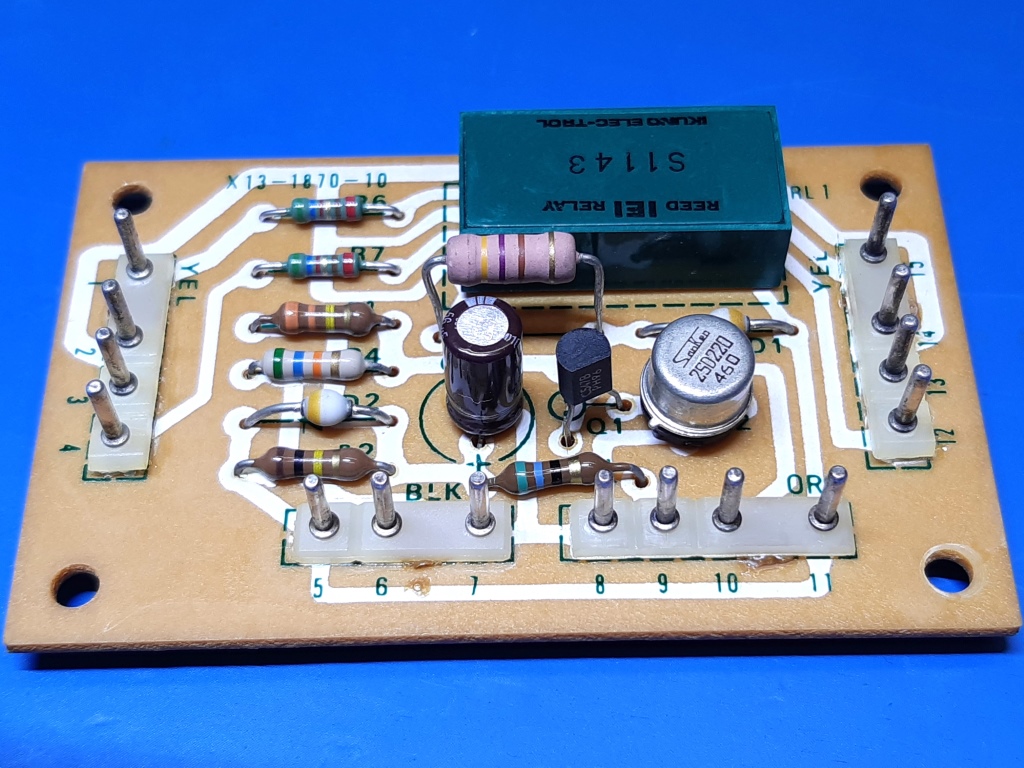
Output switching relay block (X13-1870-10
The relay block switches on the outputs, after a turn-on delay. Q1 is replaced by a BC547B, as it was a type suspect of deterioration when getting old.
C1 47 uF 25 volts was replaced by 56 uF 35V Nippon Chemicon SXE, and a 470 ohms composite resistor was replaced by a 2 watt inflammable one. It is in series with the relay and is missing in the schematic!
The two 56 Ohms resistors in series with the signal switched by the relay are replaced by metal film ones, also those are NOT on the schematic of this circuit card!
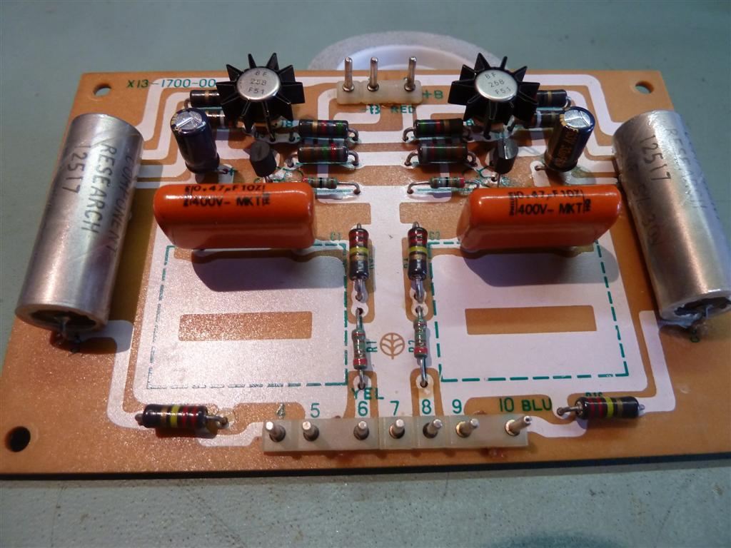
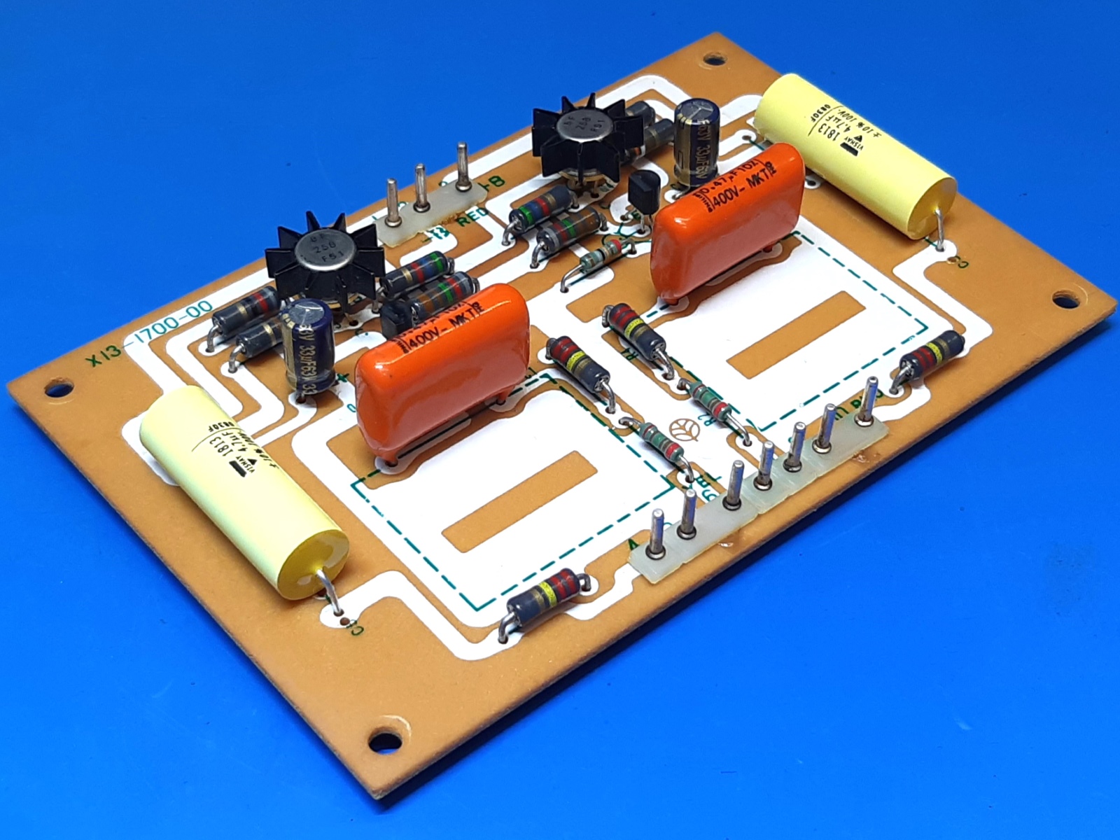
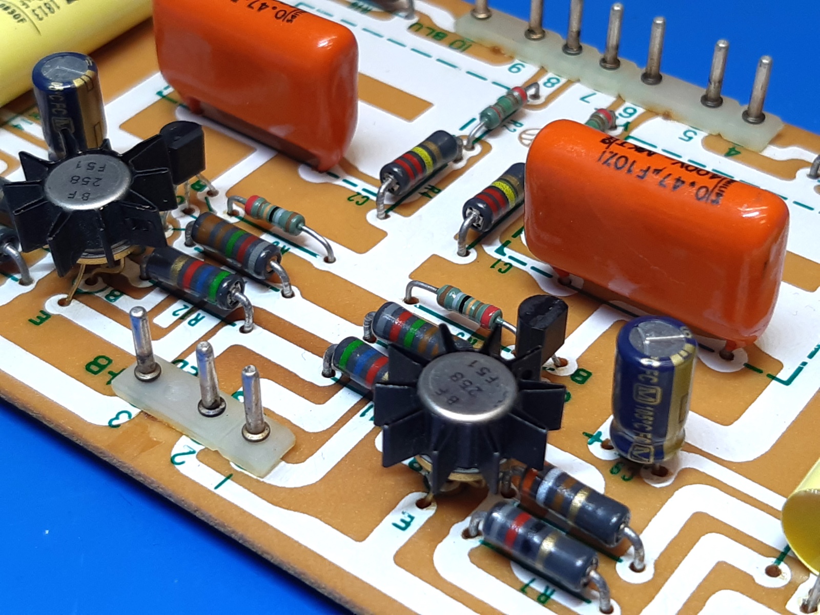
Buffer amplifier block (X13-1700-00)
The buffer amplifier buffers the inputs, microphone amp or equalizer amplifier. This card, employing + and - 50 volts, suffered from two resistors having the paint burnt off.
Because of the dissipation those 5k6 resistors were elevated a bit, the others were done the same way.
2014 situation:
Replaced parts:
| NPN transistors, BF258 | All resistors | Input capacitors 0,47uF Philips MKT |
| PNP transistors, KSA992 | Smoothing caps 33uF 50 Volts, 33uF 63V Panasonic | Output 3,3uF bipolar by 4.7 uF Vishay 1813 |
2024 situation:
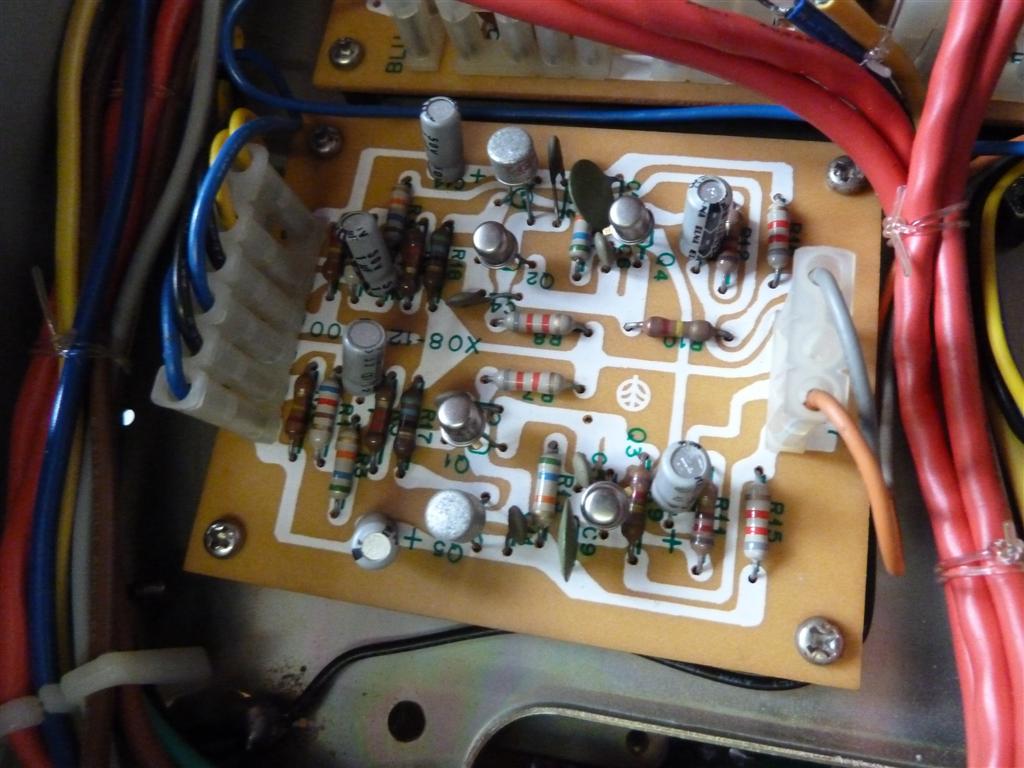
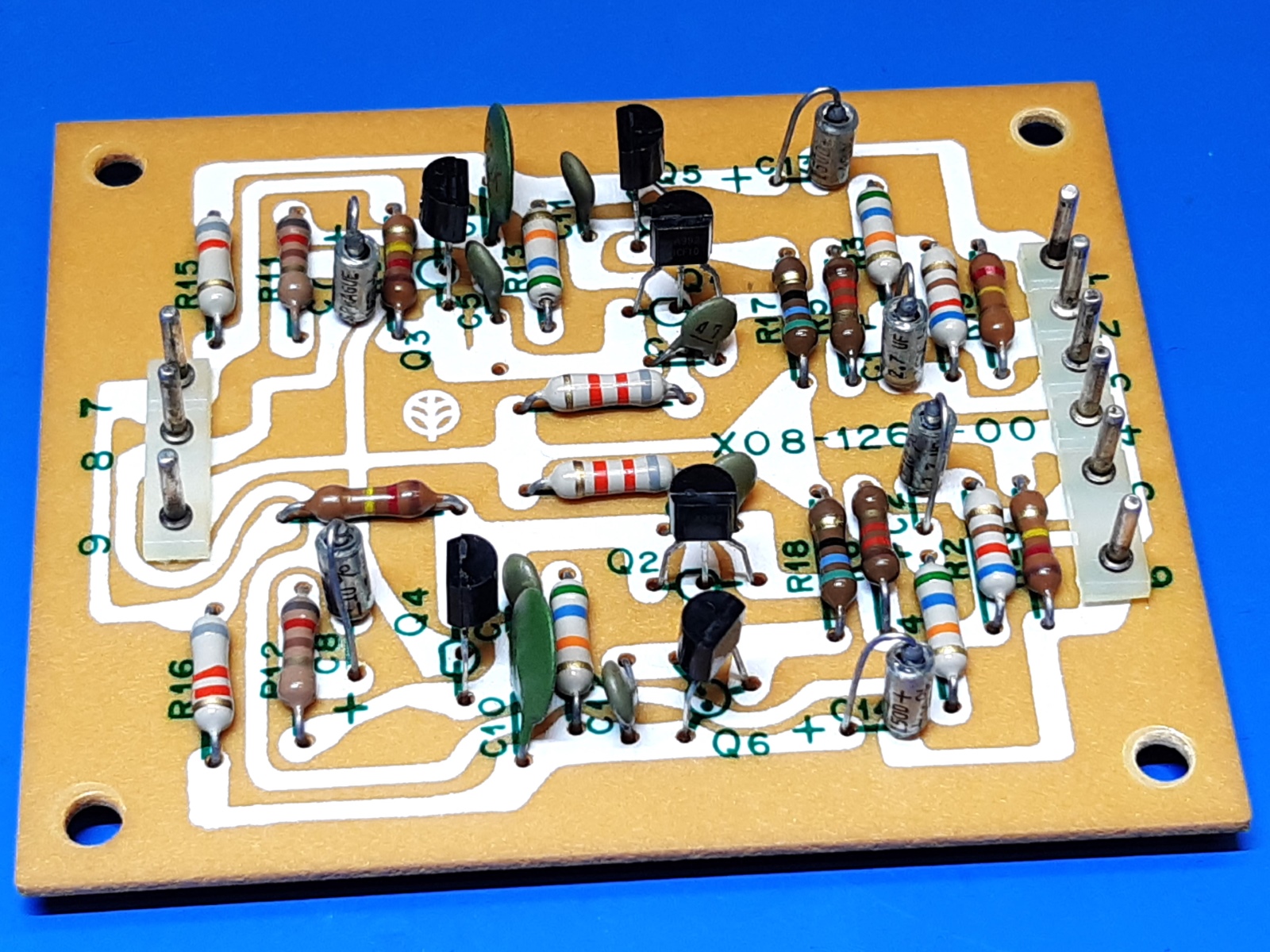
Microphone amplifier block (X08-1260-00)
The mike amp is a stereo one.
The 1 uF 50 volts and 2.2 uF 25 volts electrolicic capacitors were all changed for 2.7 uF 15 volts metal tantalums,. Cm13 and Cm14, being the output capacitors, have their marking the other way around on the circuit card, versus the schematic. I mounted it as designated on the circuit card, theoretically this is the good side.
the NPN output transistors were exchanged for BC550C, PNP ones are KSA992
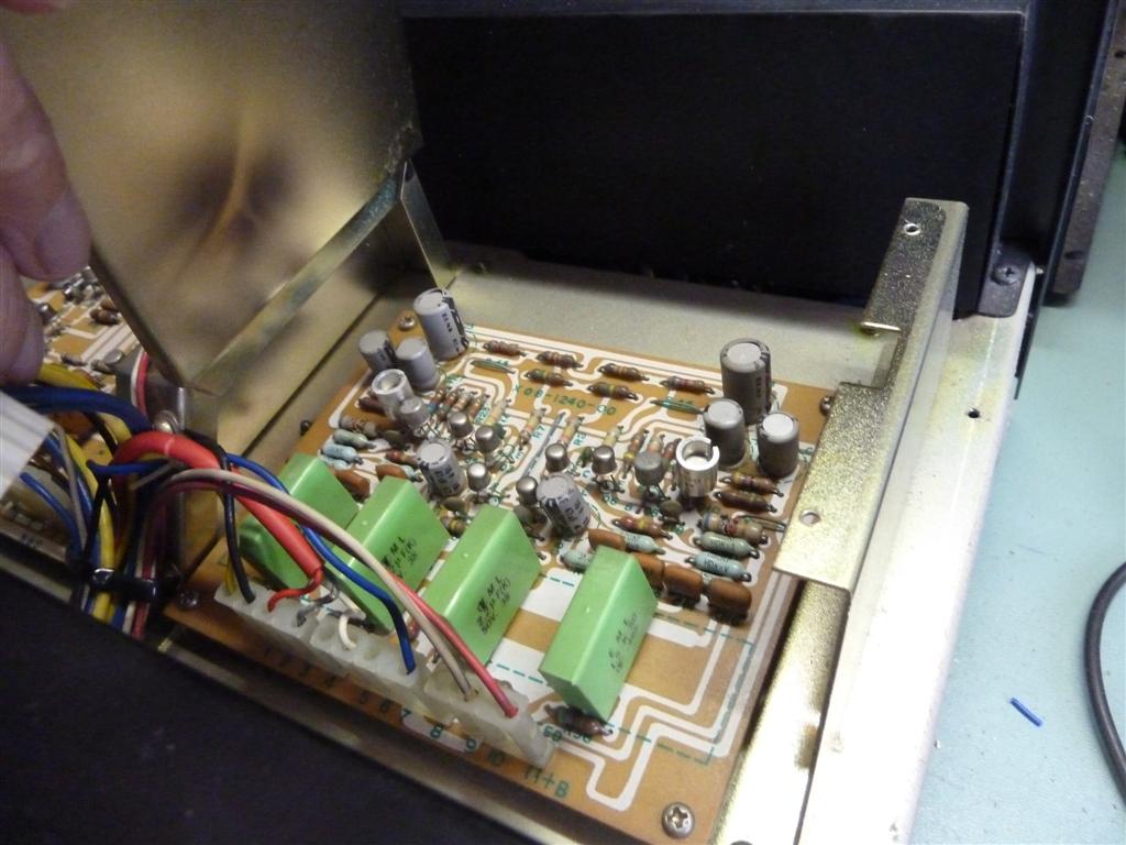
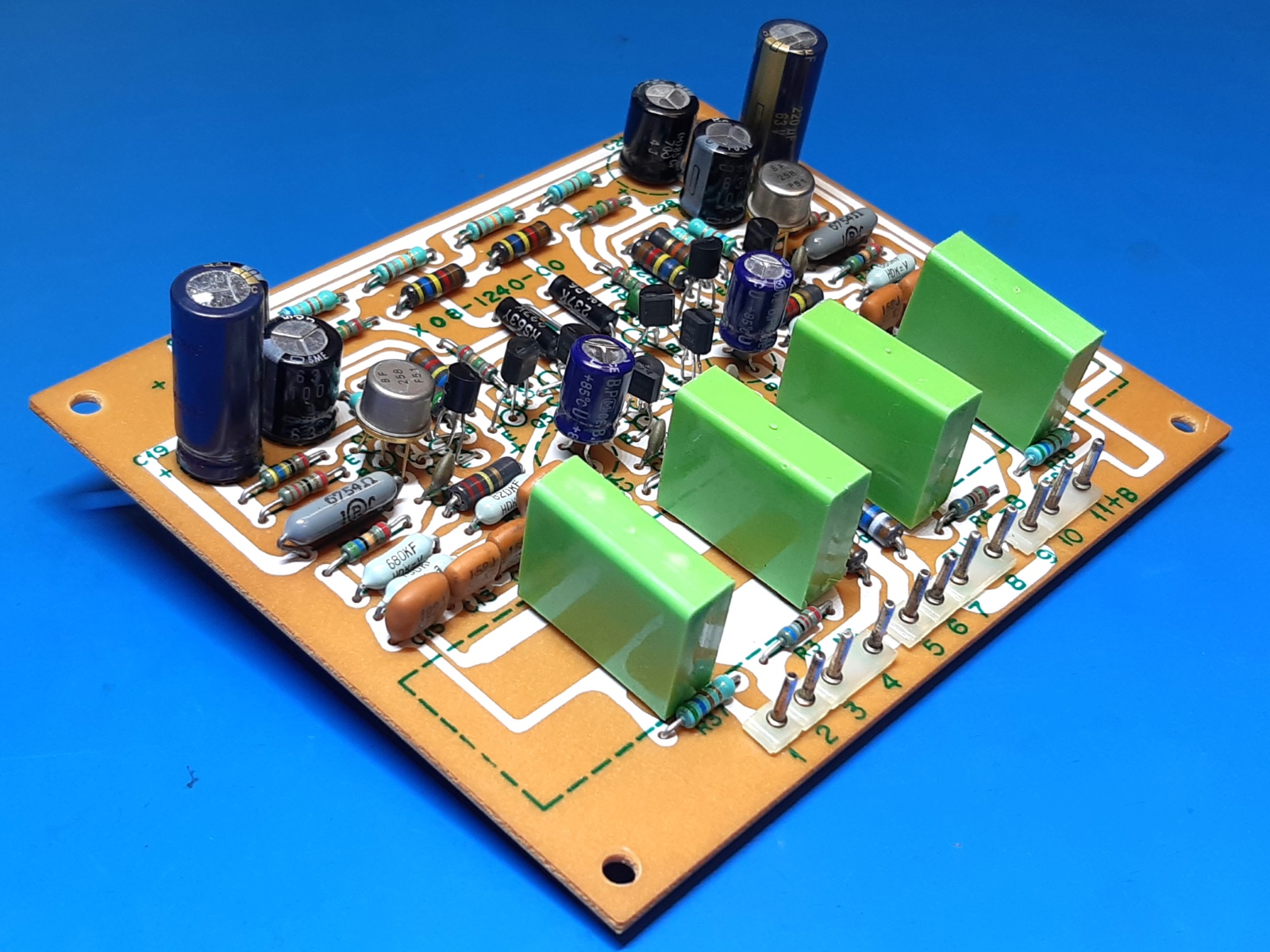
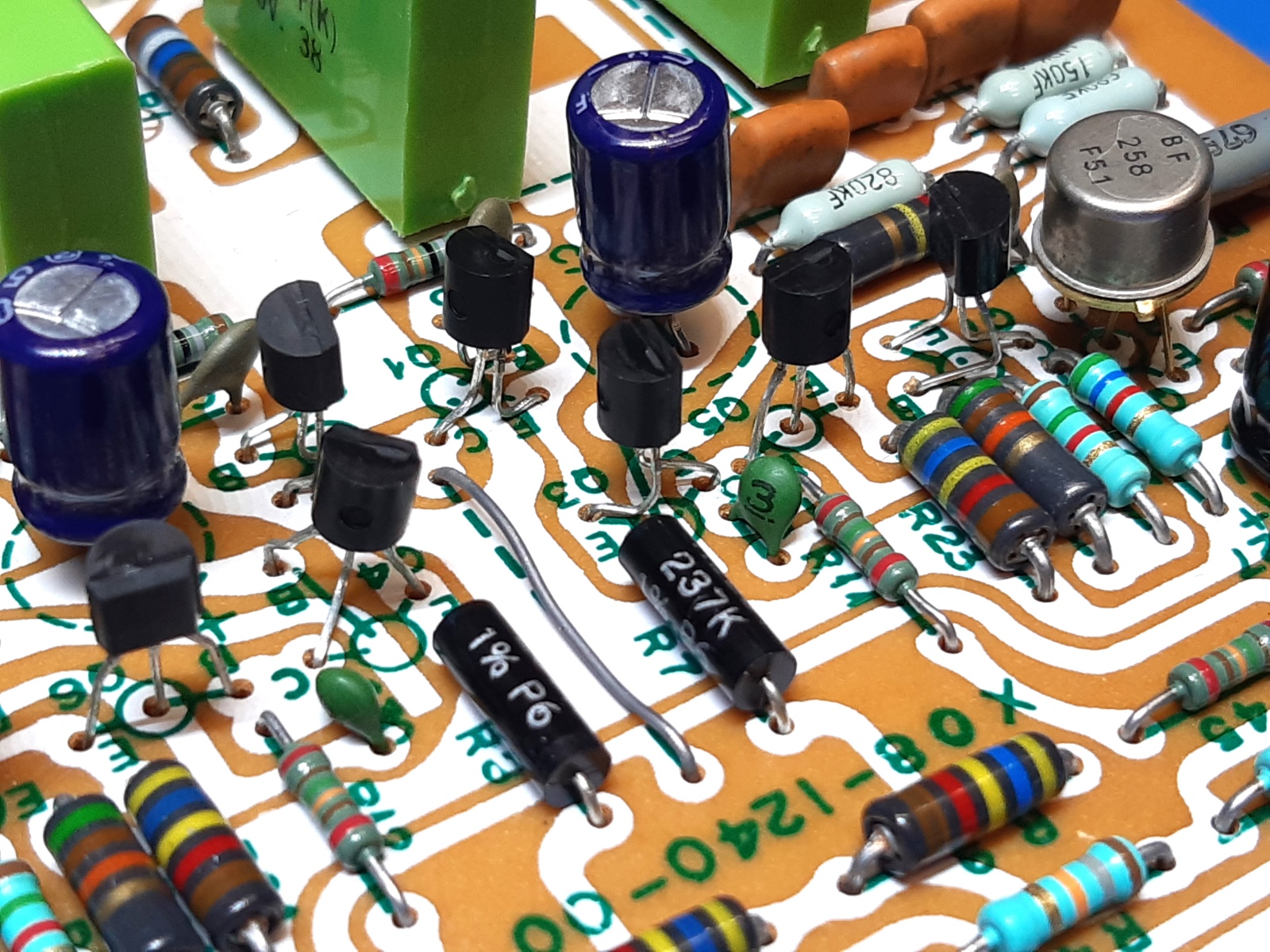
Equalization amplifier block (X08-1240-00)
The turntable amplifier board has resistors in its output heating up and losing paint, they are replaced.
The NPN output transistors were exchanged by selected BF258, its drivers by KSC1845.
At the bottom of the board two 10 nF CK05BX bypass capacitors were mounted, Cd25 and Cd26, they were in the schematic, but not on the board physically, so why not...
All resistors not metal film, are replaced by metal film ones.
Replaced parts:
| Q7,8 KSC1845 | C7,8, 47uF Panasonic Bipolar//470nF film. | C23,24,27,28 33uF -> 100uF 63V Nippon | R35,R36 6k75 1 watt |
| Q1,2,3,4,5,6 KSA992 | Q9,10 BF258 | C19,20 220uF 63V Panasonic FC | C25,26 10nF Philips |
2024:
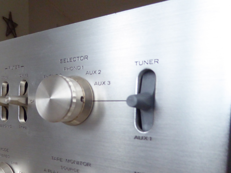
A picture of the damaged switch cap.
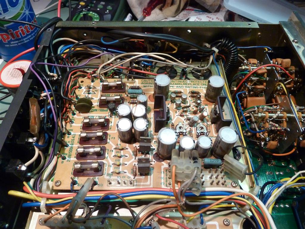
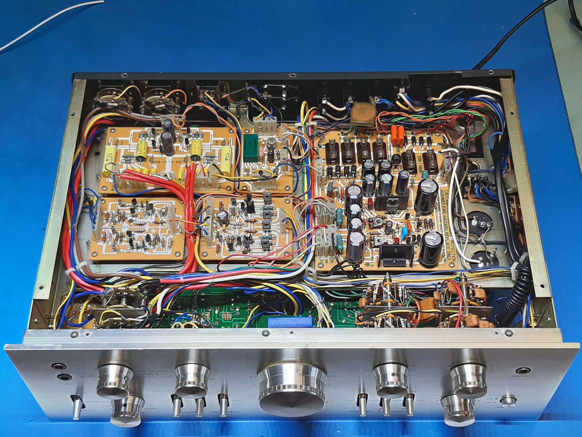
The boards, partly repopulated and cleaned, but before troubleshooting. Situation during 2014!
Somebody not even knowing me was so kind making a new plastic switch cap for me! This was not easy since the cap is hollow!
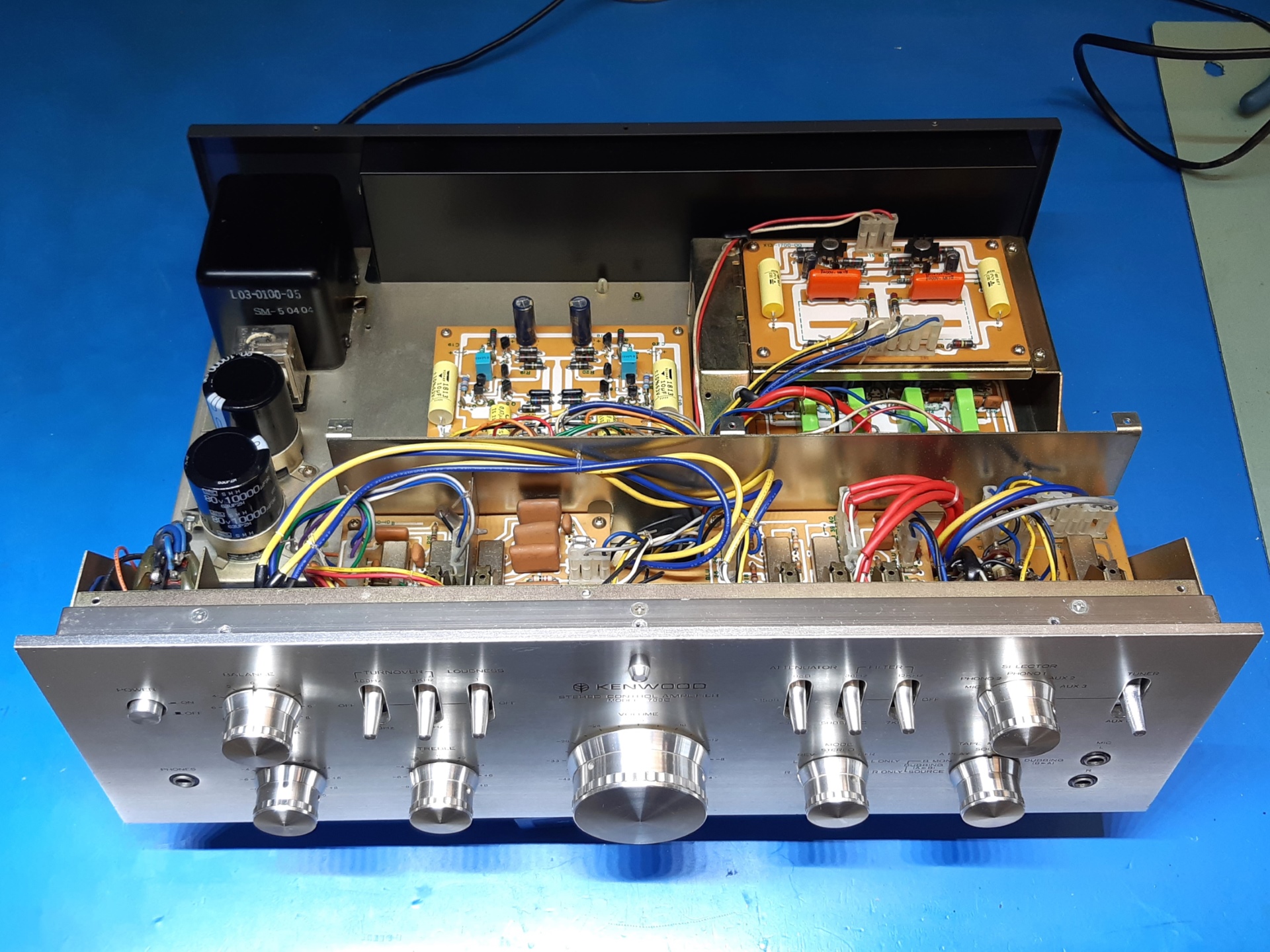
Pictures made november 2024, after revisiting/adapting some more parts:
I painted the most-right plastic toggle switch knob, I am not good at that, maybe one day I find this spare knob. Still, at a first glance, the knob does not distract me when looking at the amp.
Ga naar Gerards page / go to Gerards other pages ---->>> ![]()