Ga naar Gerards page / go to Gerards other pages ---->>> ![]()

armstrong 521 refurbishment / recap / modifications
![]() Gemakshalve is deze pagina alleen in het Engels geschreven.
Gemakshalve is deze pagina alleen in het Engels geschreven.
![]() This page is written using English language only.
This page is written using English language only.
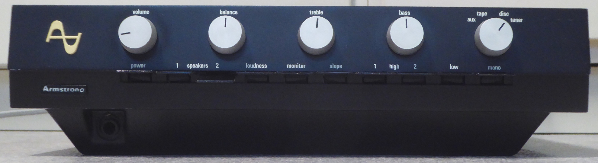
- Its looks are still very good, considering its age, all knobs work well and it came including the special loudspeaker plugs.
- The sound coming out of it was very distorted, it was tried up to about 1 Watt of power, subjective sound level.
- Sometimes an audible "tick" came out of the amp itself. It is unknown, where it came from, possibly out of one of the big capacitors.
The following refurbishment plan emerged:
Save the partly germanium transistor setup if possible (this did not work out).
Go for long term reliability and good sound, not for originality of the innards.
Components replacement based on parts on-hand, all electrolytic capacitors will be regarded as end-of-life and they will be replaced whether still good or not.
The sequence done was more or less:
- check the main amplifier card transistors
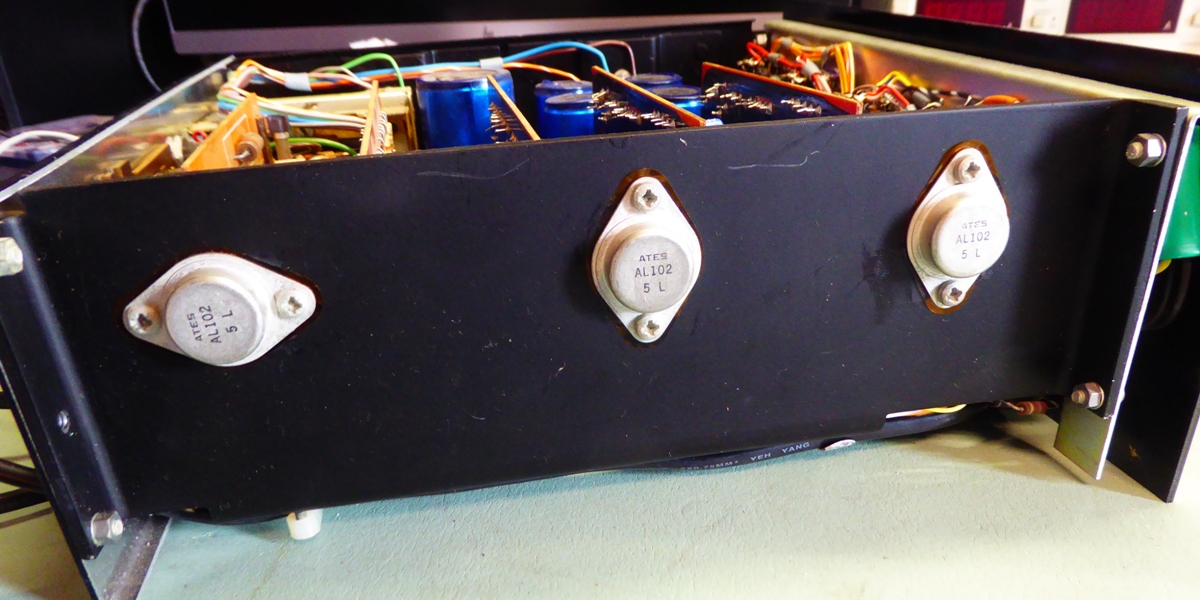
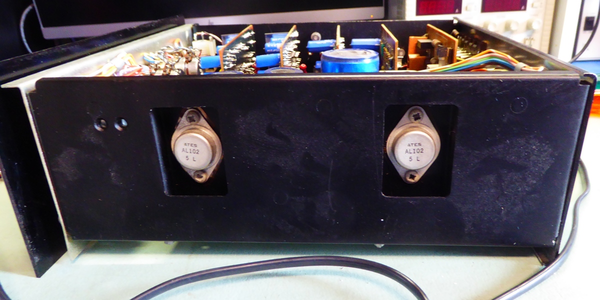
- check the five big AL102 transistors on the heat sinks
- check the big capacitors for being operational
- renew and adapt the main amplifiers to the silicon replacements for the AL102 transistors
- renew and adapt the power supply to the new situation
- renew parts on the preamplifiers
- replace the big capacitors

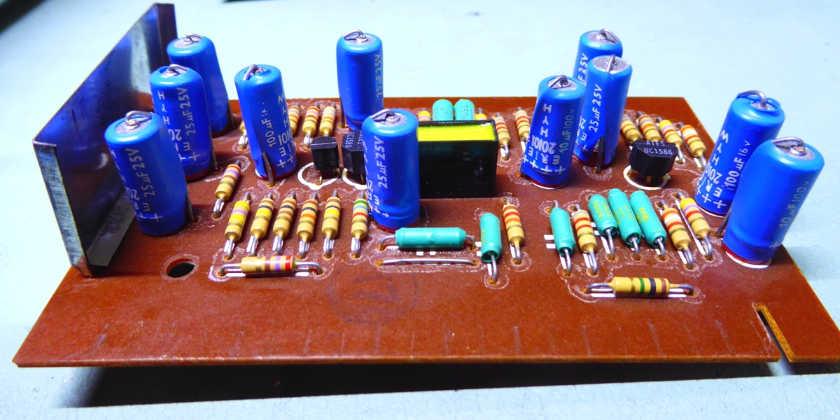
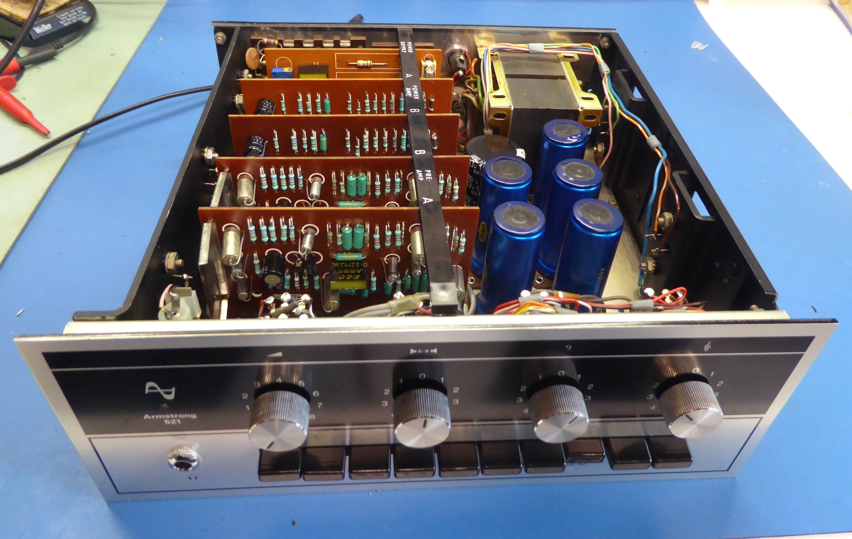
Main amplifiers, circuit card type A15
Since first testing the amp, only a very bad sound came out, refurbishment was deemed needed.
It was decided, to check all transistors by taking them out, as well as the little NTC type of resistors.
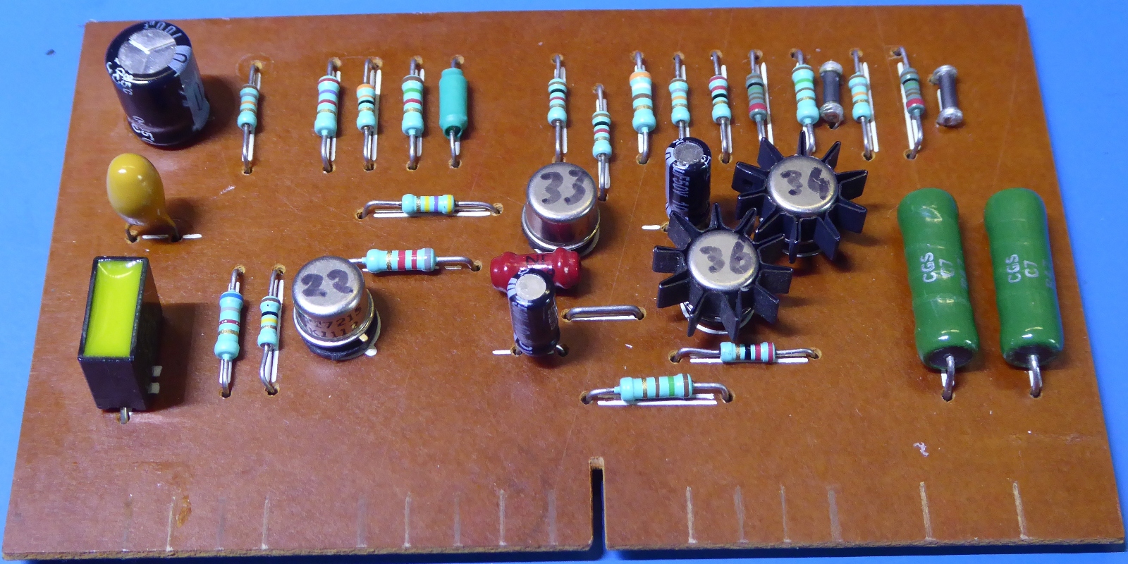
The NTC resistors, being the two little black "things" mounted on the top right in the picture of the amplifier card, and the one three positions to the left from that, measure between 10 and 15 k Ohms when cold. They are in good shape as they react by heating them up a little.
The on-card driver pair transistors TR34/TR36 are having a 80 HFE figure on both cards, the very same type BSV44A mounted as TR33 has around 115 HFE on both cards.
It was concluded, the HFE selection was probably carefully selected during production, so it was concluded best practice to leave them as is.
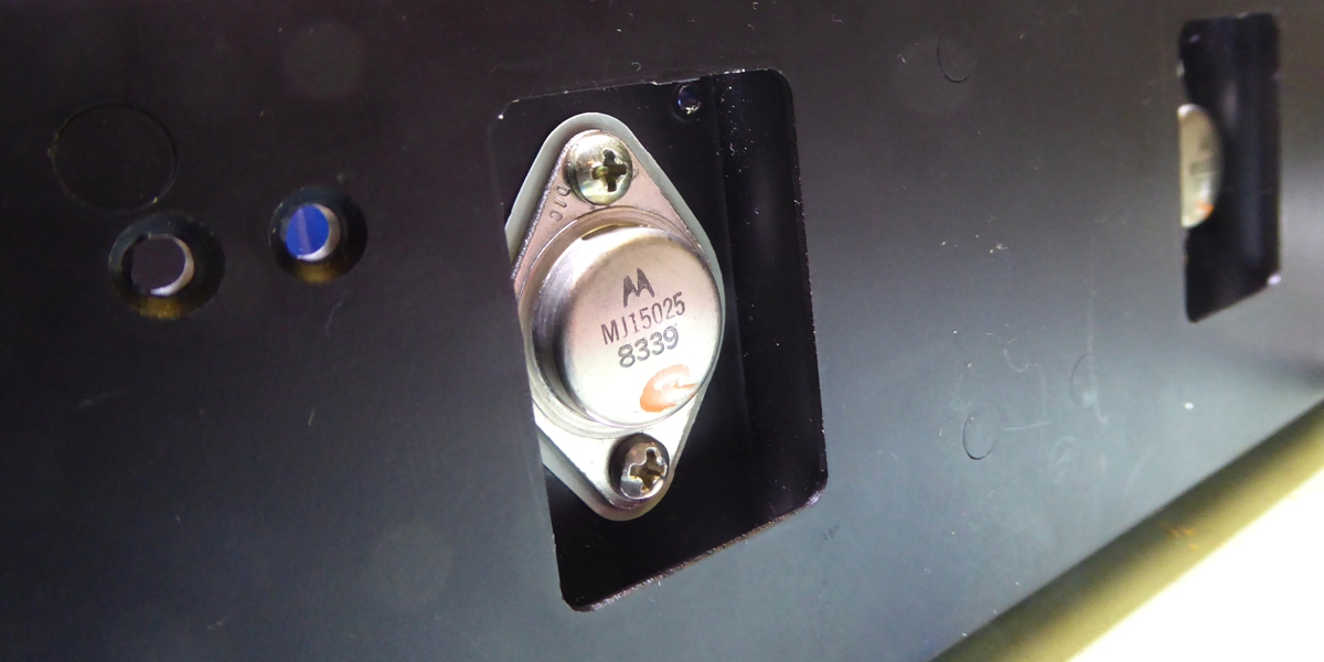
However, two out of the four AL102 output Germanium transistors appeared to have a very low HFE (8 and 12), wich would limit output current needed.
As insufficient Germanium high power/high voltage transistors were unavailable, it was decided to adapt the amplifier for a Silicon type of output transistors.
Selection of resistors, matching output transistors and driver transistors, as well as power supply voltage are all critical (read: the design is unforgiving) and must be checked and evaluated.
Actions:
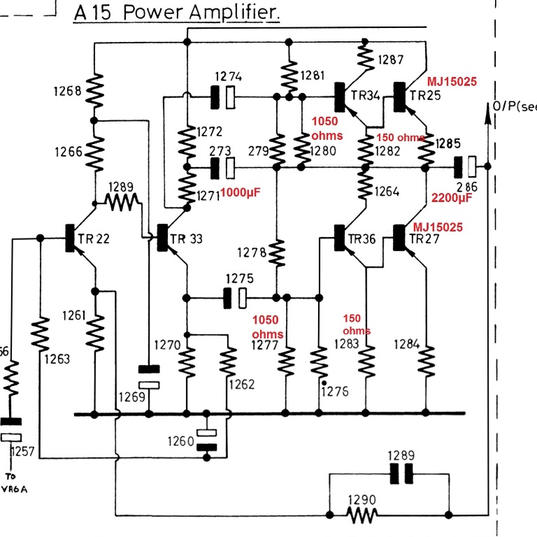
- Replaced the base resistors of the output transistors by 150 Ohms ones, instead of 51 Ohms, to make up for the VBE change of the Silicon MJ15025 transistors used.
- Replaced the 750 Ohms resistors mounted parallel to the NTC resistors by 1050 Ohms ones, for the same reason.
- The "1260" capacitor was replaced by a tested low leak Tantalum one, as it is fed through a high ohms resistor.
- The chosen capacitors to drive the output stage were replaced by low-impedance Panasonic FR ones.
- All small resistors are replaced by (mostly NOS Philips) metal film ones.
Result:
- A small 0.07% distortion at around 5 Watts output, 0.2% distortion at 20 Watts/ch 1kHz sine wave continuously
- Bias current of around 25 mA for output transistors @ power supply voltage tweaked to 51 Volts.
- No thermal runaway and quite stable bias current over temperature range.
The bias current is just a chosen value, it could be less or more, by tweaking the power supply voltage a little bit. This current is very power supply voltage dependent resulting from the design.
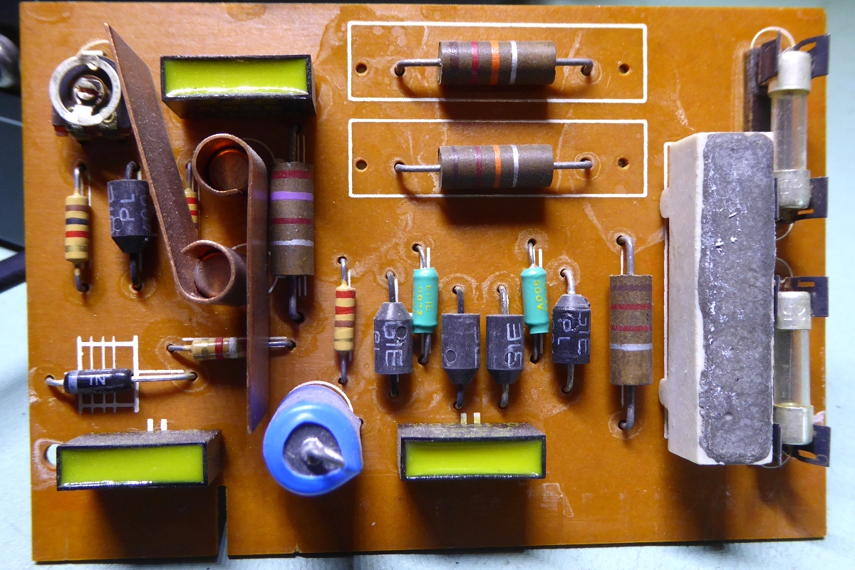
Power supply, circuit card type A17
- As the power supply output reacted on the setting of the 220V / 240 V selection, it was considered insufficient for use, because of the amplifier bias current dependency on the voltage.
- The AC139 germanium transistor TR28 did leak about 1 milliamp when measuring , probably influencing the poor performance.
- Later, when the power supply was being rebuilt and tested, it was found the big 2.7 ohms resistor went hot and smelly during a 2x15 watts output of the amp and above that the output lowered from 50 Volts to around 45. This also implies that all the internet comments of the amp able to supply 2x25 Watts I consider as marketing lies or at least lack of knowledge. In the end, its manufacturer originally stated 15 Watts.
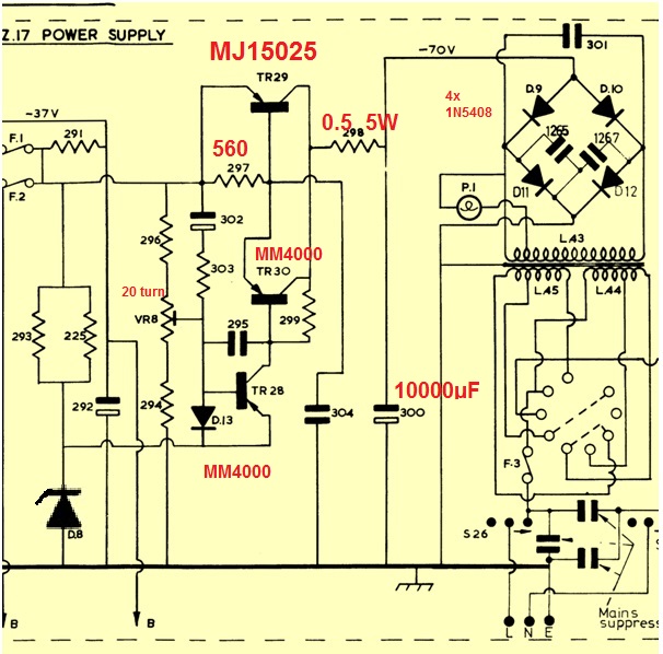
- Replaced the "298" 7W resistor by a 0.47 5W resistor to get rid of heat and have more power available, as there are no vulnerable Germanium transistors to be protected, anymore.
- Replaced the trimmer resistor by a 500 ohms 20 turns trimmer. As only 500 Ohms was on hand, the 294 resistor became 1.2k instead of 1k, and the 296 resistor became 4.3k Ohms
- Replaced the two on-board transistors by MM4000
- Replaced the power diodes by 3 Amp 1N5408 ones, needed because of them feeding a bigger smoothing capacitor and higher expected currents.
- Renewed several other parts, also with the purpose of getting rid of the partly drifted carbon composition resistors.
- Replaced the current passing transistor by a MJ15025.
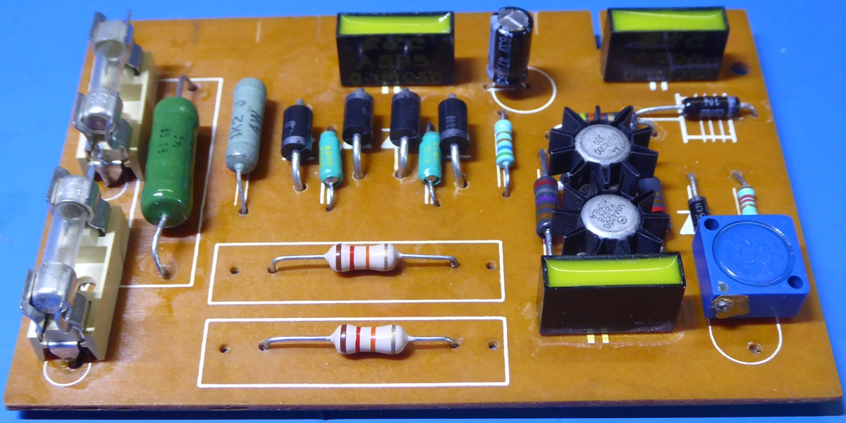
- The output voltage is precisely tunable
- The output supply voltage to the output amplifiers retains up to 2 x 20 Watts of power, instead of around 2 x 15 Watts having amplifier distortion seriously kicking in.
- The voltage selector on the back of the unit can stay on 220V setting because of the use of the more rugged parts.
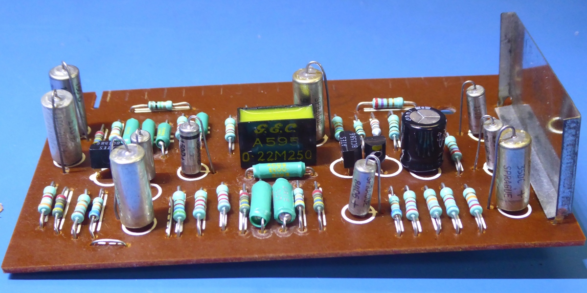
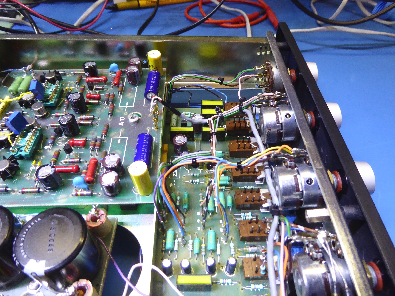
The Control unit C16
Rather large coupling capacitors were in use, it was considered justified to skimp on capacitance here and there.
The "211" capacitor is the wrong way around in the original schematic drawing, on the real board it is mounted correctly, as is the paint indication on the circuit card.
This, as the voltage on the TR19 collector is -5.2 Volts and on the 212/213 resistor intersection it is -7.5 Volts.
Several electrolytic capacitors have no voltage reference, the "201", "217", "219", "242" and "243" ones, meaning that the voltage may vary, depending on leakage in the circuit.
Transistors TR19 are low noise type BC384L , HFE is around 350, and the other ones are BC158-6 having HFE of around 115 for TR20 and 95 for TR21. They were retained.
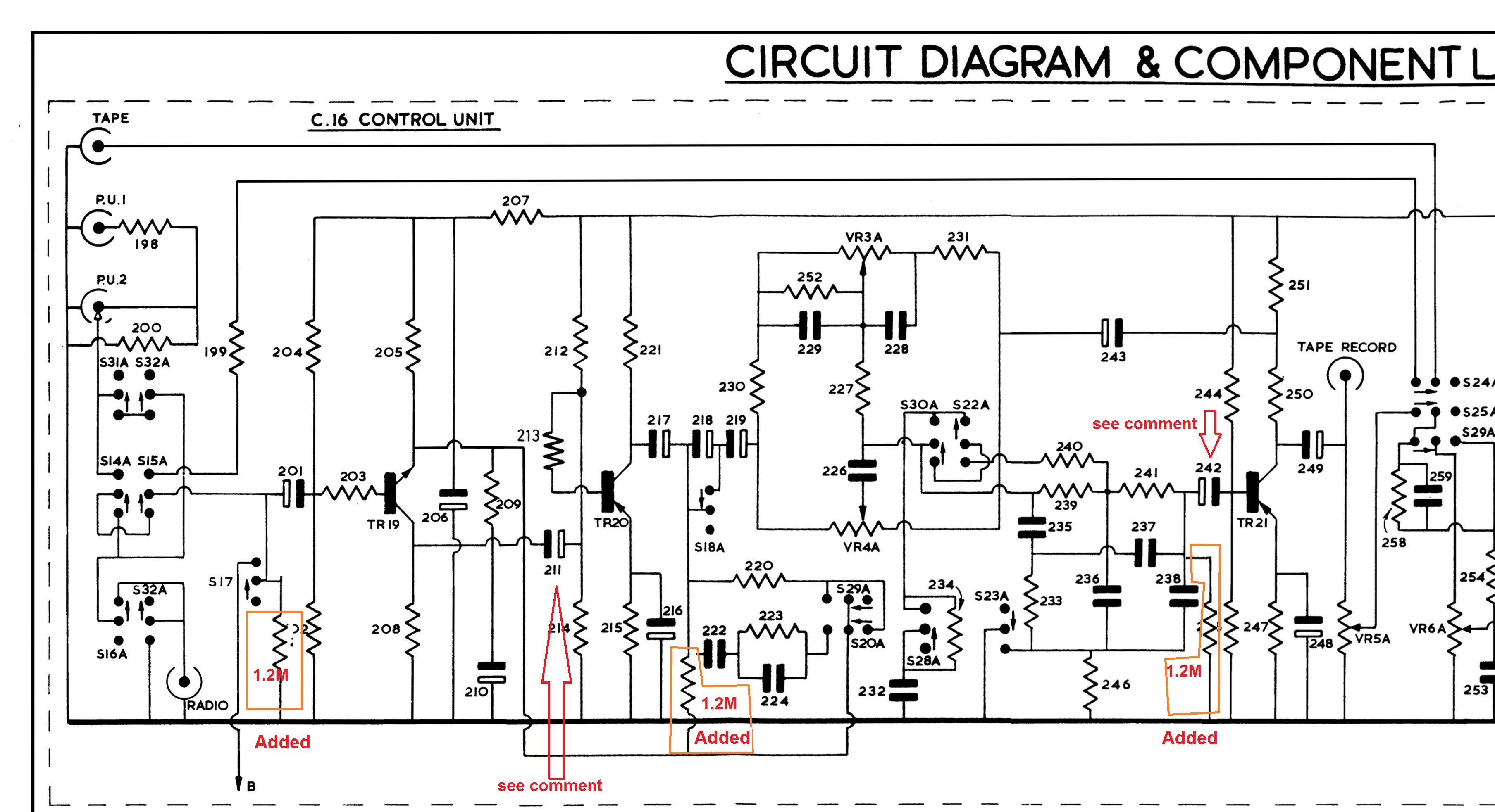
- Resistor replacements using metal film ones.
- Replacement of all electrolytic capacitors, mostly using tantalum ones.
- Adding ground referenced 1.2 MOhm resistors to the spots where the electrolytic capacitors have no default voltage reference.
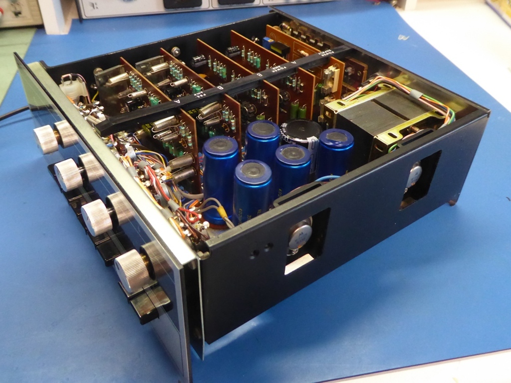
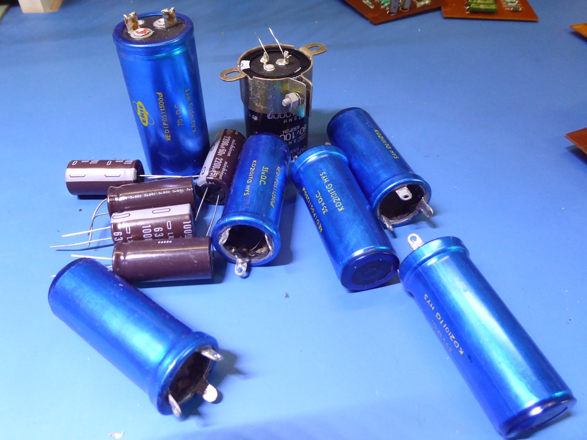
The Big capacitor replacement
Six big capacitors are mounted on the amplifier base frame.
-the "300" main power smoothing capacitor, which is a 1250 ÁF 70V rated.
-one 1250 ÁF 35V capacitor for preamp power smoothing (location "292")
-two 1250 ÁF 35V capacitors for main amplifier positive feedback circuit. (location "273")
-two 1250 ÁF 35V capacitors for main amplifier output to the loudspeakers (location "286")
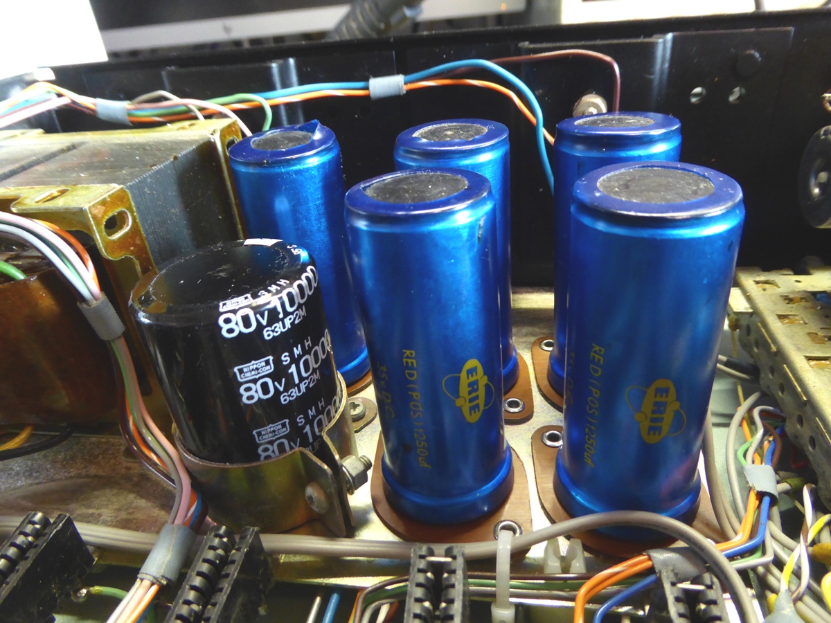
The main supply capacitor was replaced by a 10000 ÁF 80V one
The positive feedback capacitors were replaced by 1000 ÁF 63V ones
The other three were replaced by 2200 ÁF 50V ones
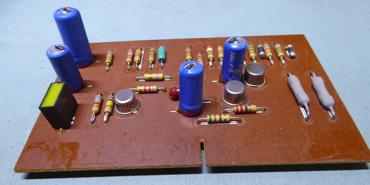
Apart from the biggest capacitor, of the other five capacitors the cans were emptied and re-used, as shown on picture on the left, below.
On the picture on the right, a grey wire is visible in front of the capacitors. It is a shielded wire to the tape output connectors, replacing a pair of long unshielded wires from the balnce potentiometer to the tape output terminals
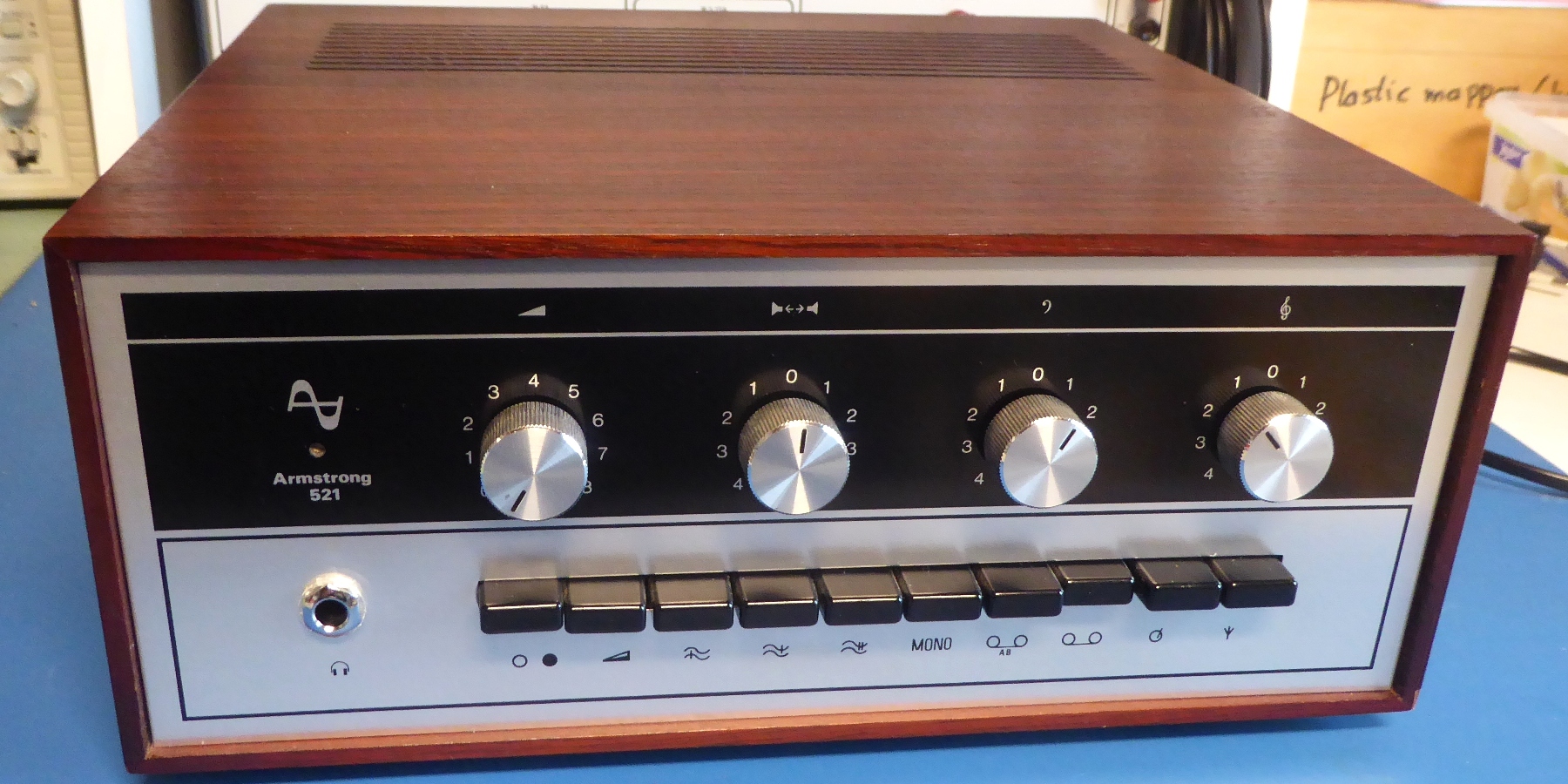
The armstrong 521

Go to my 621...
Ga naar Gerards page / go to Gerards other pages ---->>> 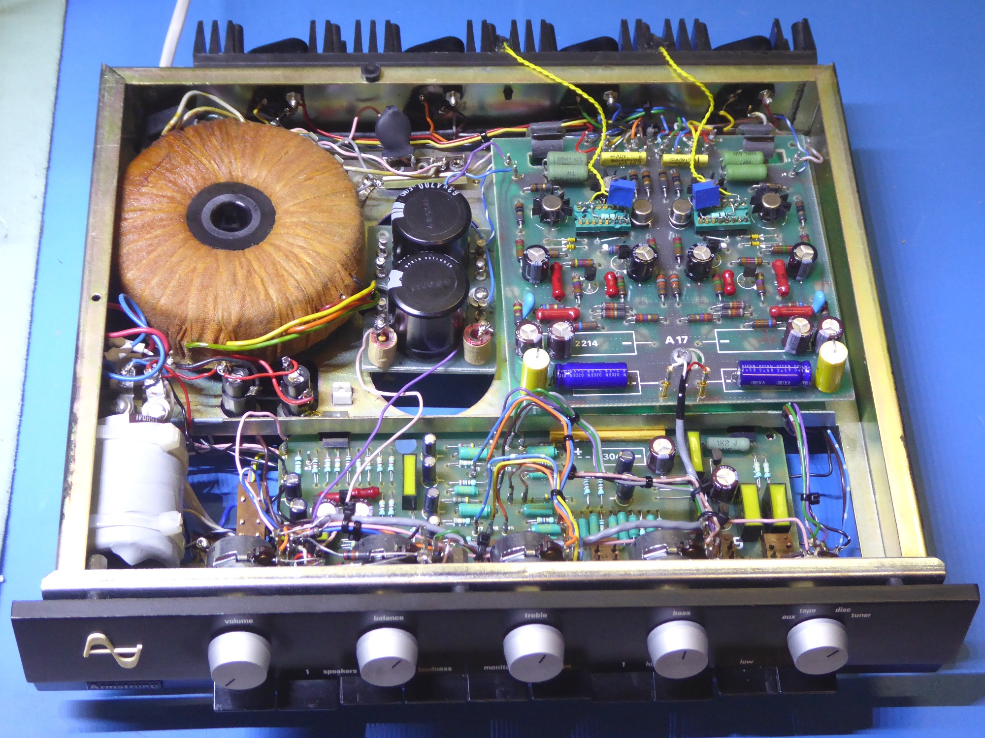
![]()