
Akai aa6600 repair / refurb 2025
This AA 6600 is for sale in the Netherlands, fixed price 250 Euros, cash and Local Pickup Alkmaar area as I do NOT ship,
I only answer if you provide your phone number also, see the moving mail address on my main page.Gemakshalve is deze pagina verder in het Engels geschreven.
![]() This page is written using English language only.
This page is written using English language only.
I bought this Akai as a defective piece, it was sold to me as needing attention/fixup.
Initial testing showed one channel hardly present (95% soft crackling and no music), the other channel did sound bad, but music was more or less present.
Most probably such, situation is caused by the preamplifier or potentiometers and switches. The FM radio part was still capable of receiving, which was promising.
Partly, the black paint of the knobs faded, underneath is the gold/brownish color of the front "rings". This is irreversible so I regard it as "patina" rather than take effort to paint the knobs area supposed to be black. ;-)
As always, the aim of this page is to help out fellow technicians, and share useful repair information.
It assumese a working technical knowledge, as well the ability to find the manuals on the www.
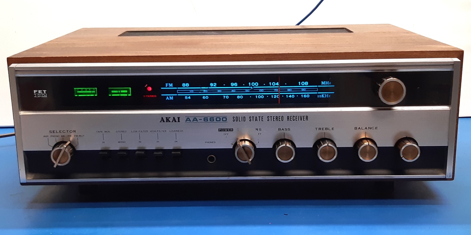
This very sturdy built old receiver now sounds good again!

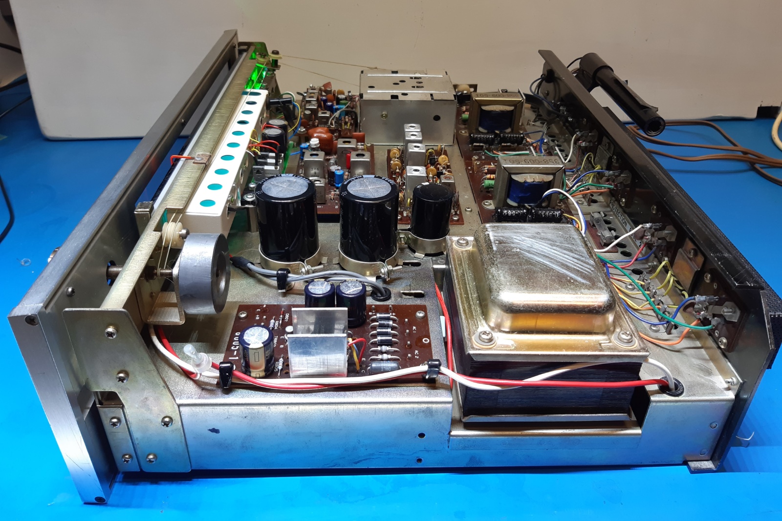
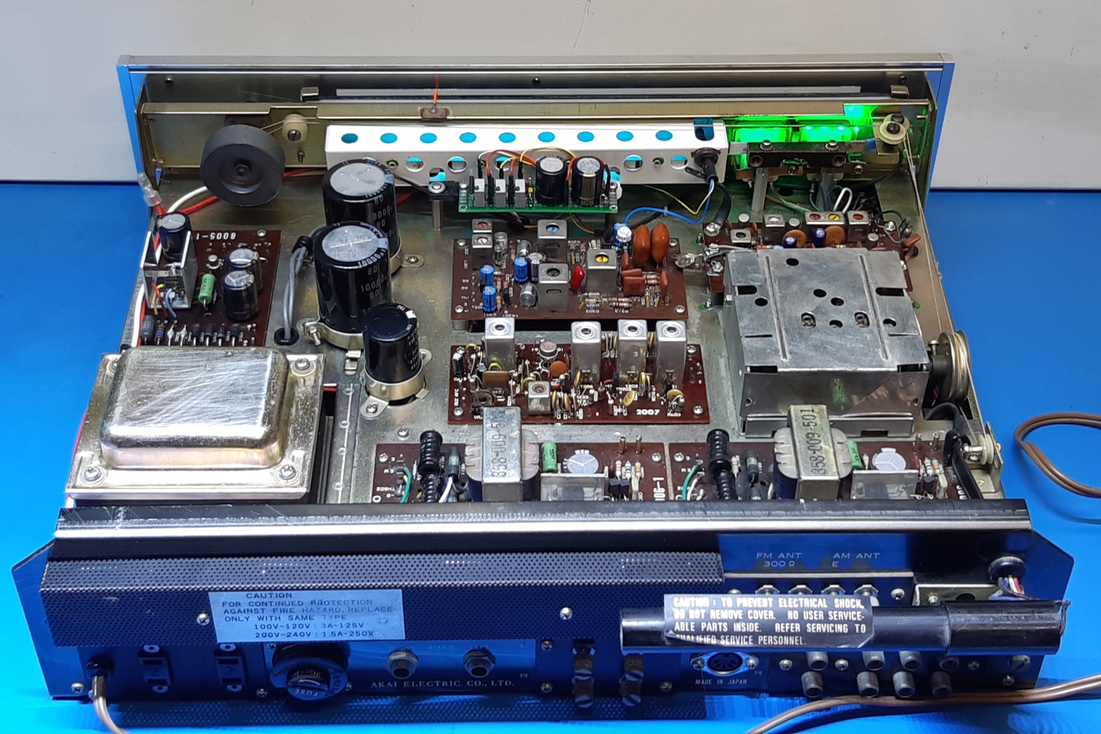
A look at the not-yet-refurbished receiver.
It still looks pretty good, but part of the text legends on the front are gone. At the back, it looks a new DIN socket for the tape I/O was used as it was shiny, there are Jack connector loudspeaker outputs available and a set of screw terminals.
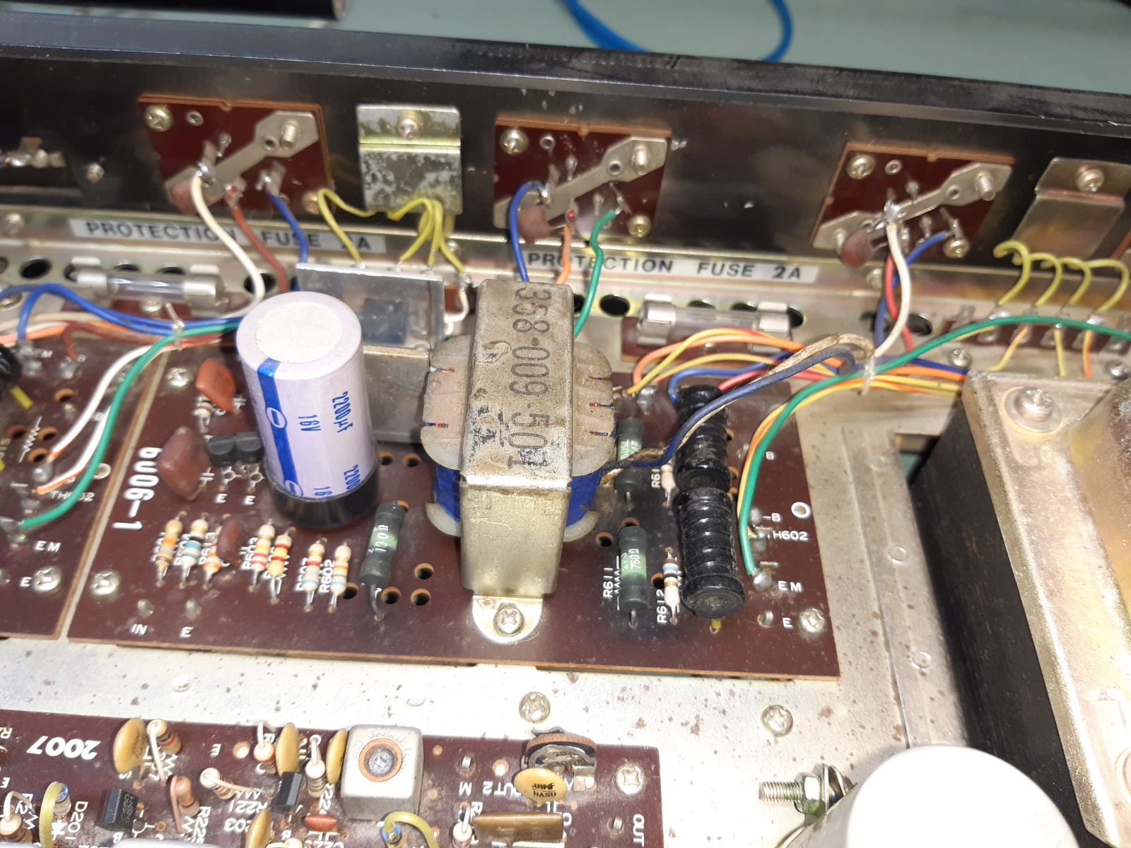
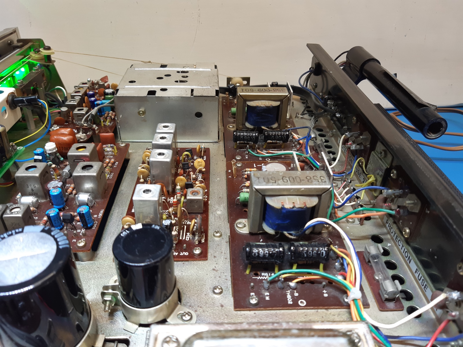
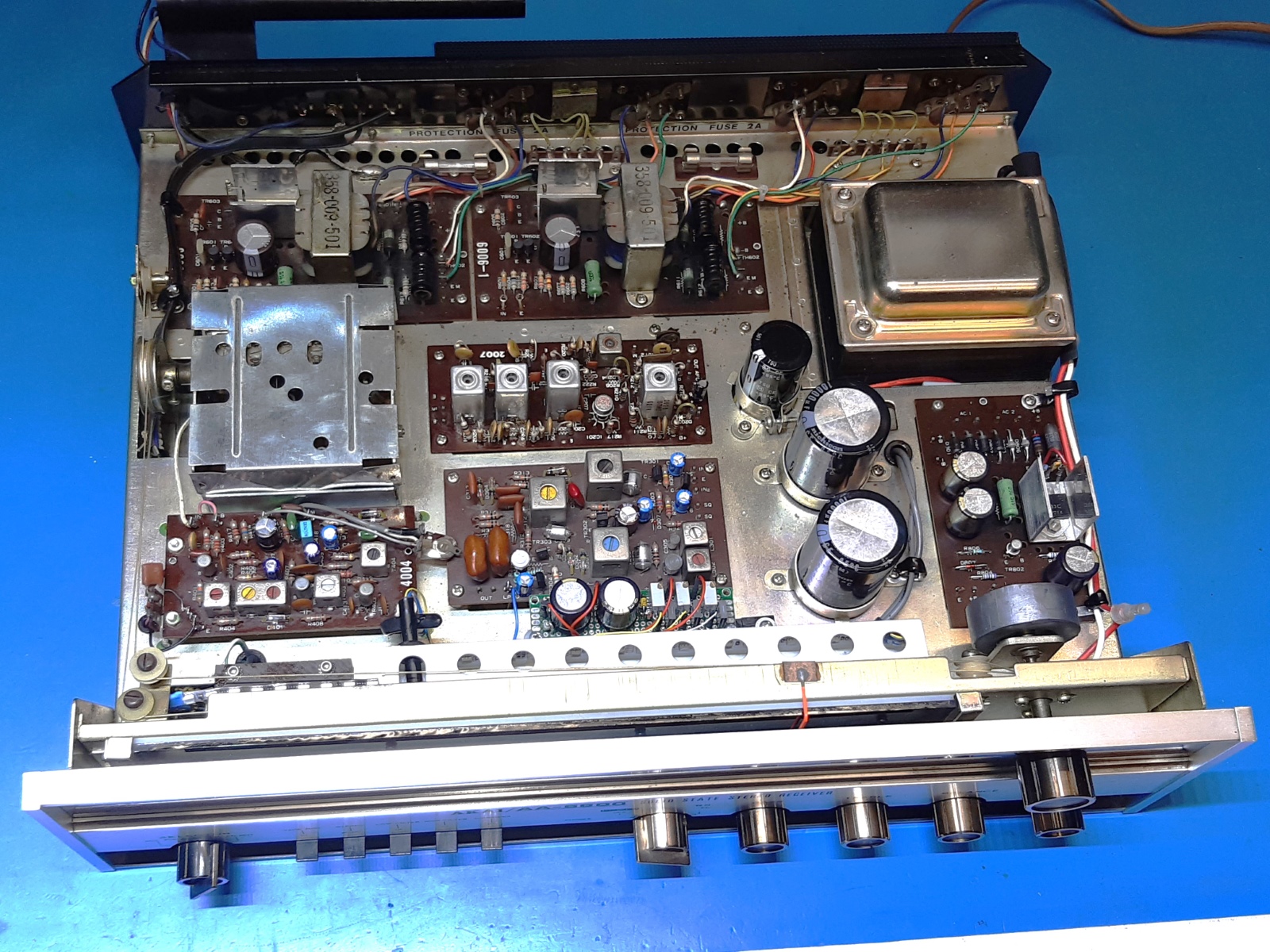
Opening up the receiver, a major eyecatcher is the transformers steering the current output stages of the amplifier, something you will only see at late sixties/start of seventies era of solid state receivers.
The receiver looks roomy enough to be able to proceed in steps instead of totally take it apart.
Visible is a repair at the small input pair of transistors in one of the main amplifiers (European BC237 replacements were used), so a main amplifier was once repaired.
Unfortunately, I forgot to make overview pictures of the whole receiver old situation.
According the things I encountered, this receiver probably was repaired more than once.
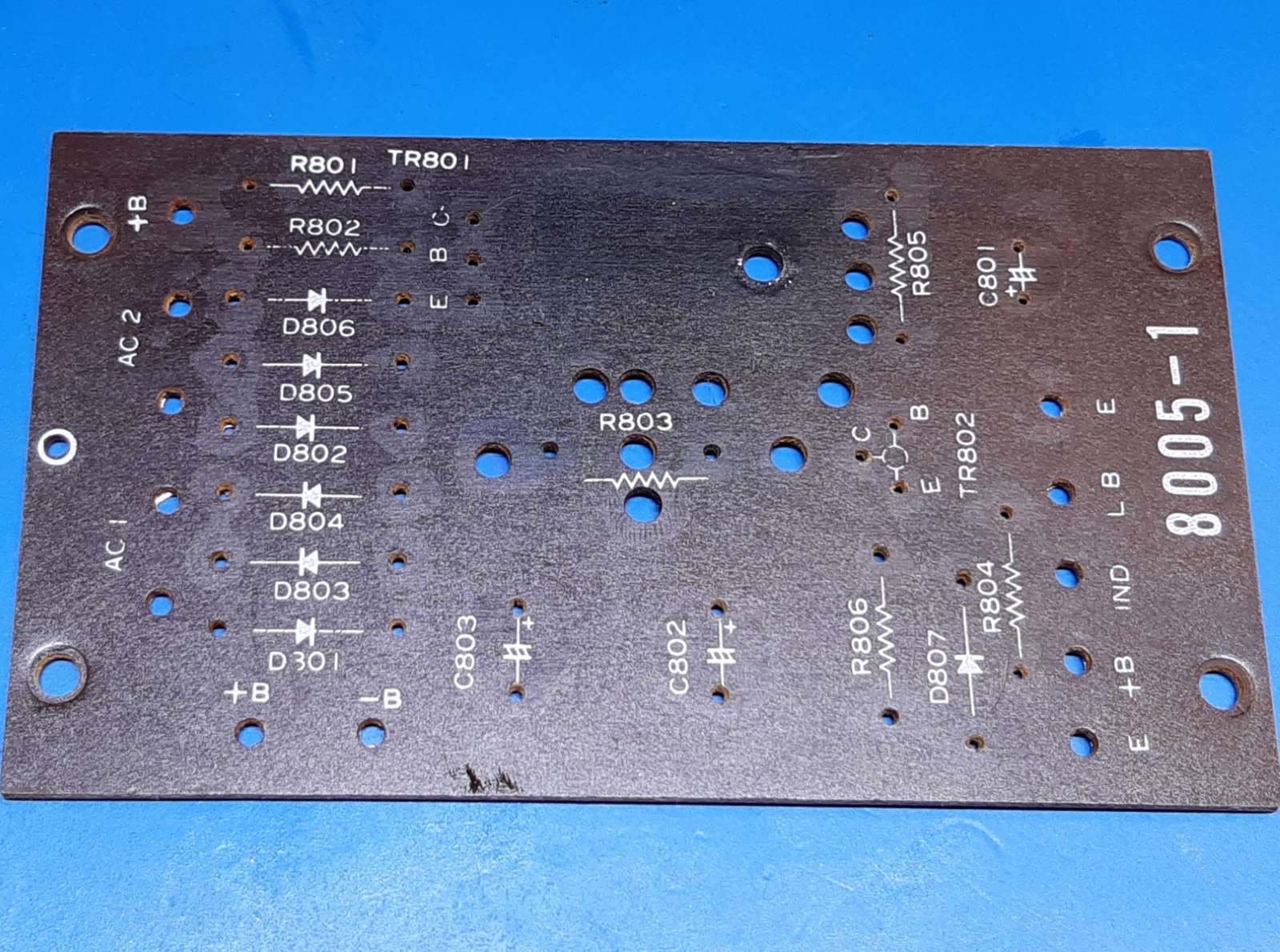
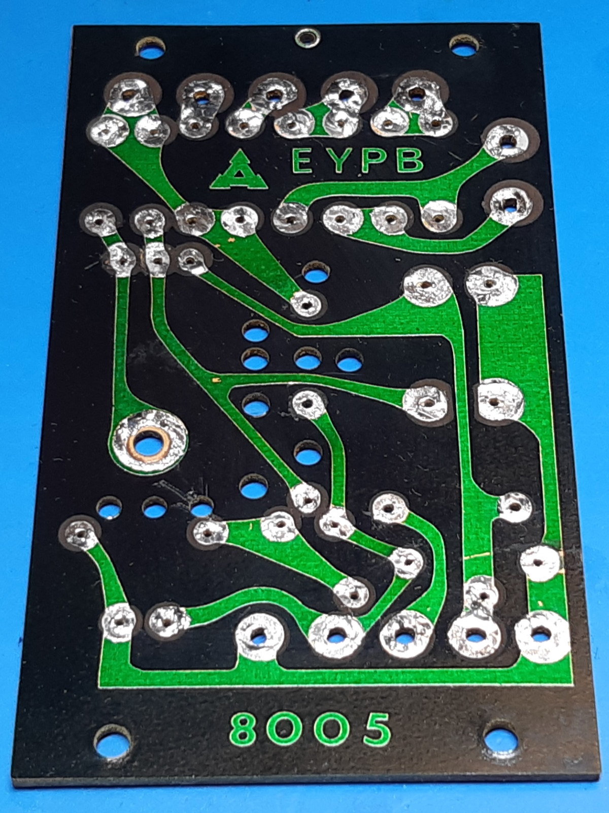
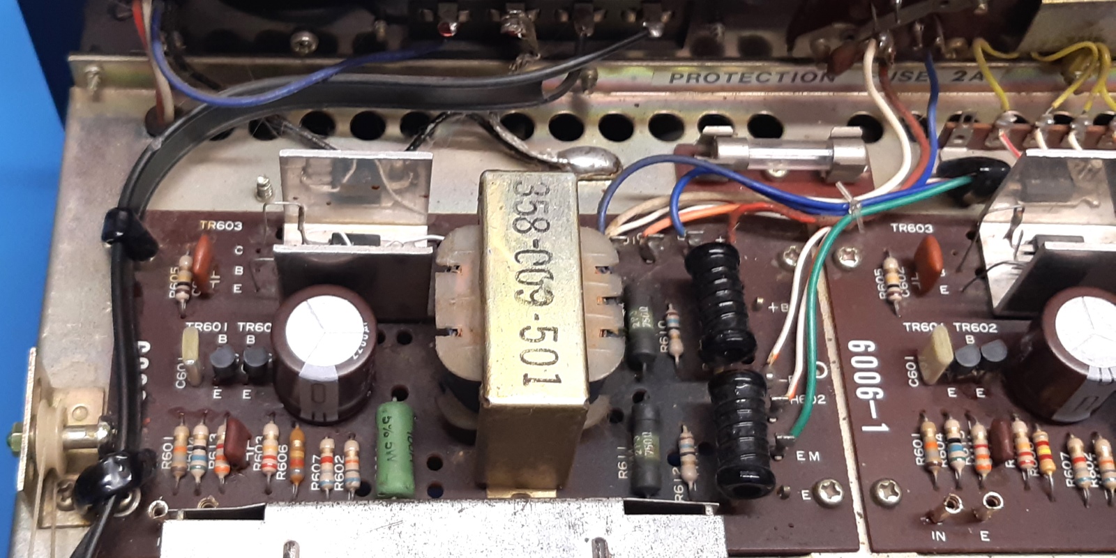
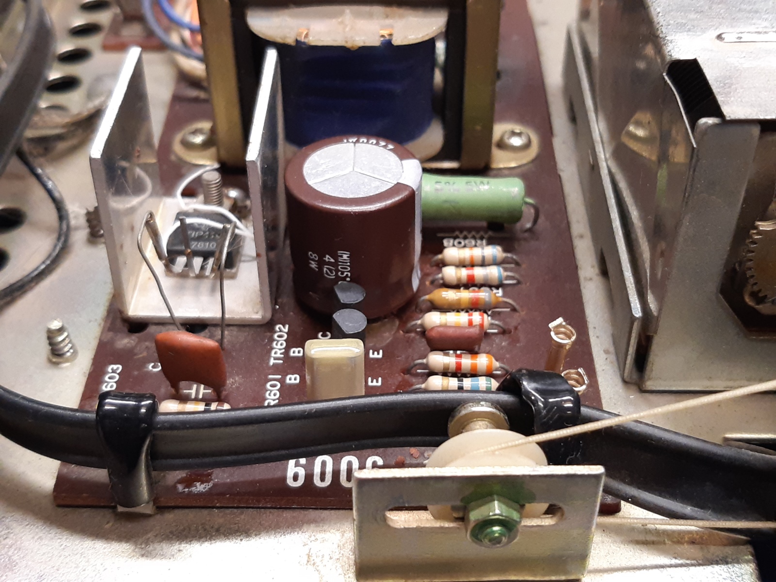
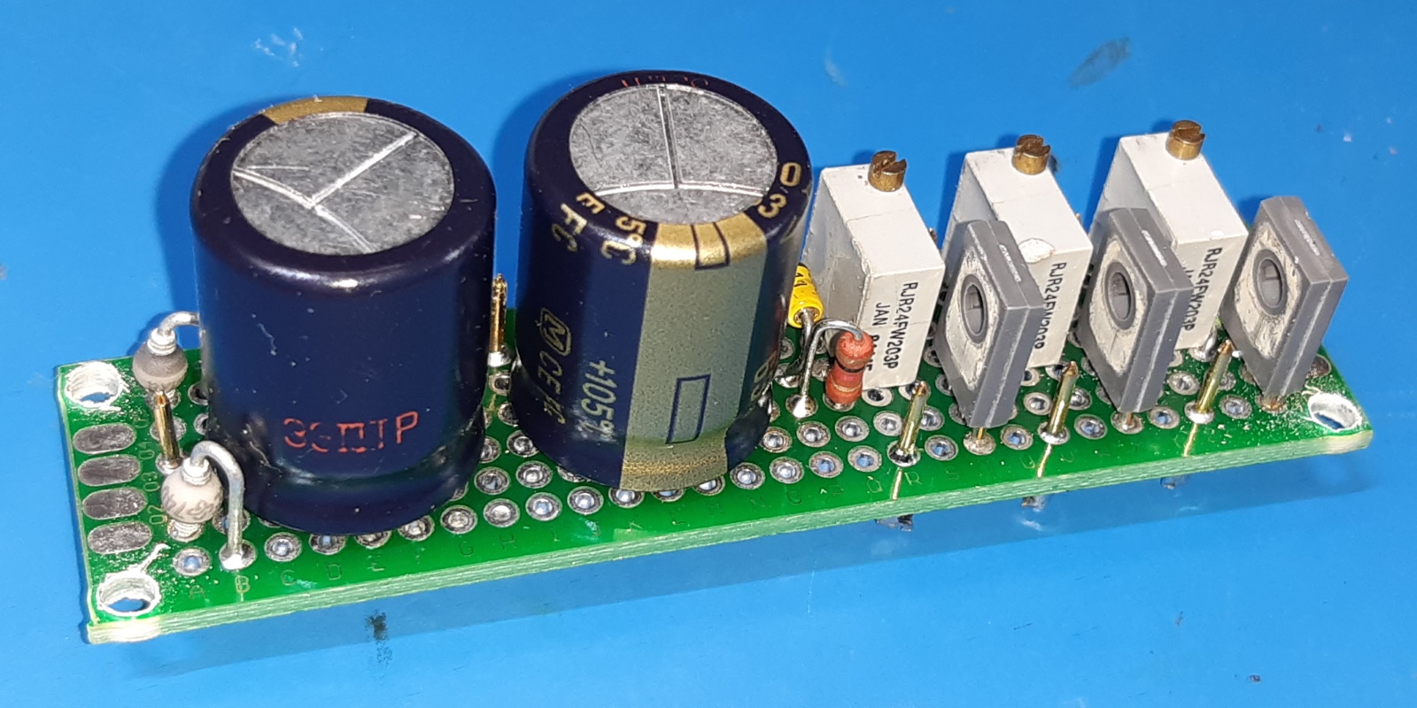
The Akai aa6600 power supply card 8005-1
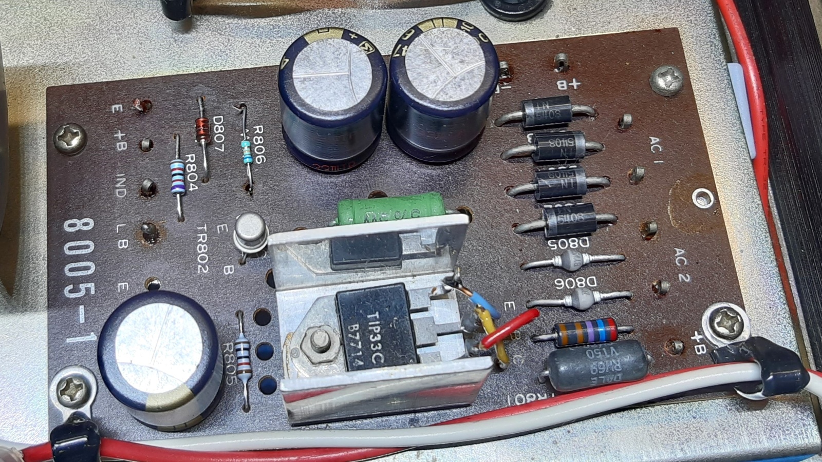
An eyecatcher is the TIP33C transistor in the power supply. This is not the original one specified, again another repair. Probably it ever failed and it was repaired by somebody wanting to make sure it would never fail again and therefore did choose a high power one. Wanting to reburb this supply card, I will retain this transistor, I like this "overkill". ;-)
Another interesting observation is the the circuit cards themselves were produced by Matsushita, according the logo on them.
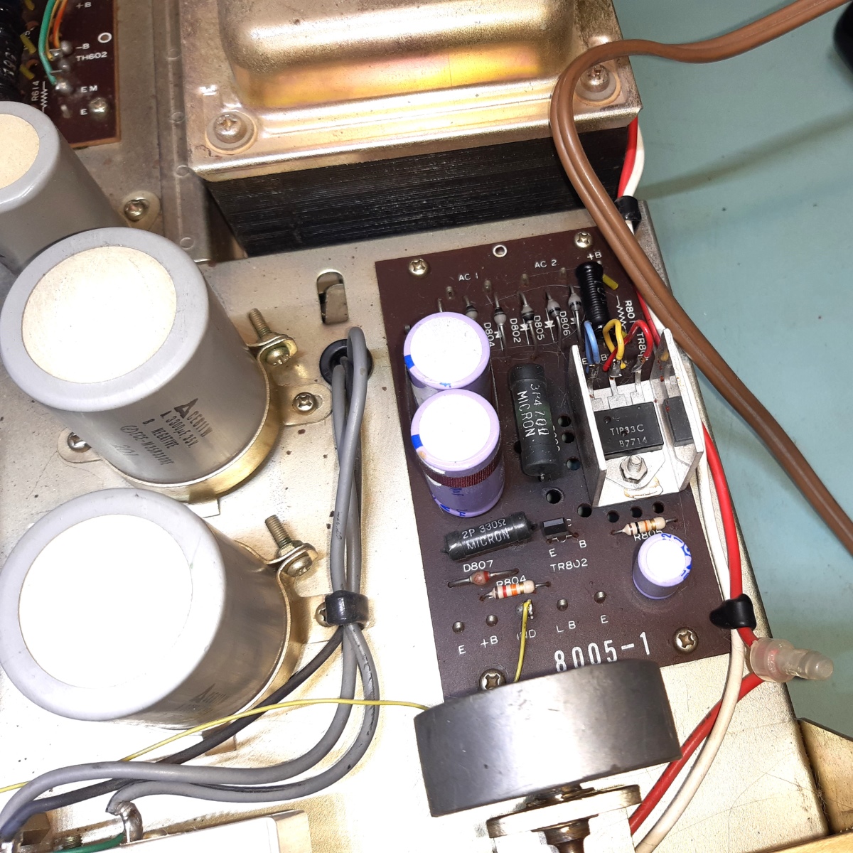
To move over a little dissipation from the pass transistor getting hot, I changed the 10 Ohms R801 to 18 Ohms.
The power rectifiers were upgraded to 1N5408, the ones for the preamp to BYV96E. The Zener diode, also supplying the 12 Volts for the tuner circuits, is a 1N4742A, now.
The electrolytic capacitors on the boards were all changed to Panasonic FC 470 uF. They are 105 degrees celcius types.
The R806 (it says on the picture but wrong in the schematic!) 330 Ohms power resistor was removed (still visible on the picture below) and replaced by 680 Ohms low wattage one.
It is for the stereo indicator, which one I replaced by a LED, adding a trimming resistor on the stereo decoder card.
The TIP33 power transistor/cooling piece was elevated by putting a washer underneath, getting rid of more heating up of the circuit card itself.
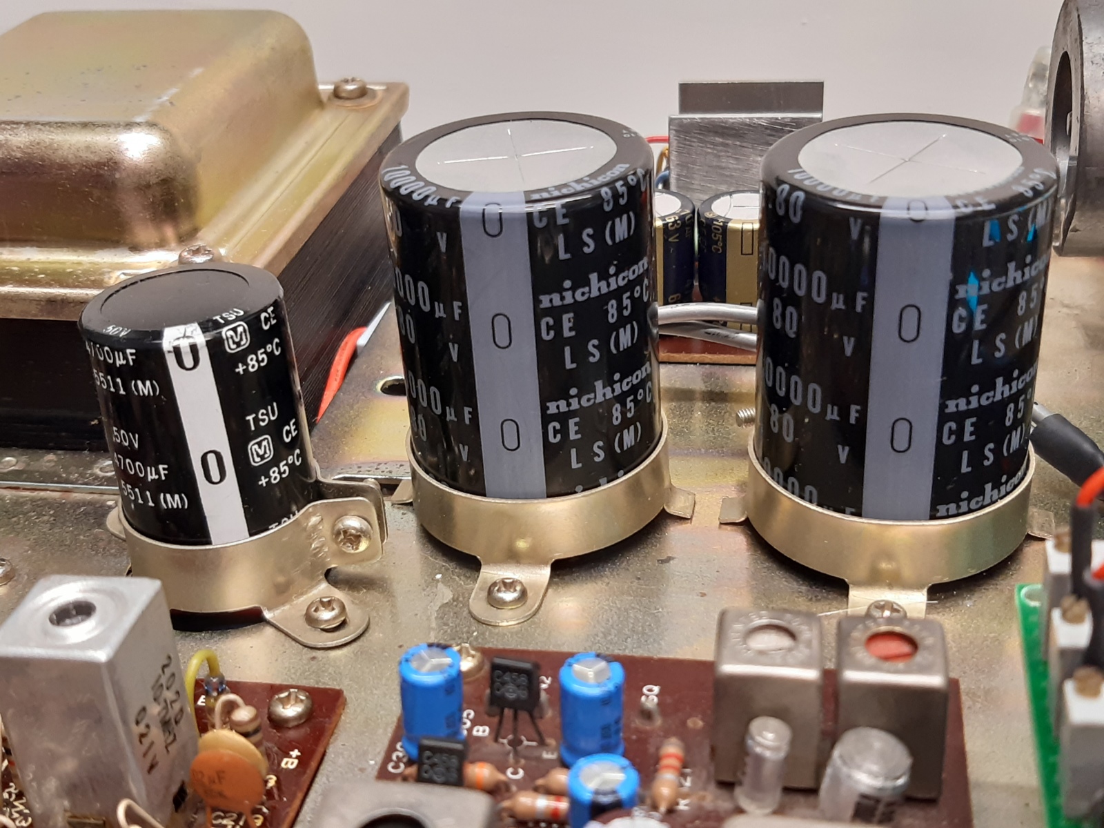
The last picture shows a 4700 Microfarad capacitor feeding the circuit card, and 10000 Microfarad 80V ones feeding the main amplifiers. A bit overkill, but I had those available.
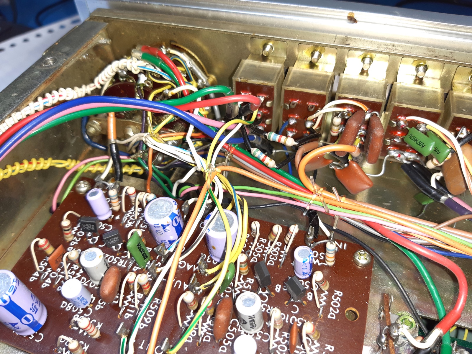
The power amplifier boards
There is no bias current adjustment on the power amplifier boards. I decided to leave the output stages, if behaving correctly. I am pretty sure, the output transistors had to be carefully selected for behaving the same and are still good, I did not attempt to exchange them. Also the 750 Ohms resistors which did change color to the heat I left in, because I have no exact suitable replacements in house.
Some of the components at the input side of the main amplifiers are replaced, described below.
The input pairs of transistors were replaced by BC547b, the input capacitors, electrolytic capacitors and the 100 Ohms discolored resistor. One was replaced by a brown one in the past.
The transistor on the cooling piece should be a 2SC931 according the schematic, but I found a TIP41C on both amp channels. Probably, it was replaced, in the past.
Also here, this overkill using a TIP41 makes it more rugged than when the receiver was new.
So, replacing the 750 Ohms resistors not really needed but remain to do "for the looks", one day.
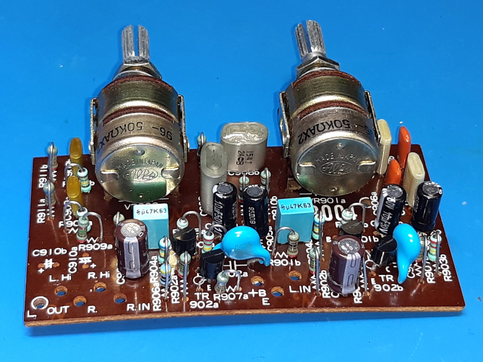
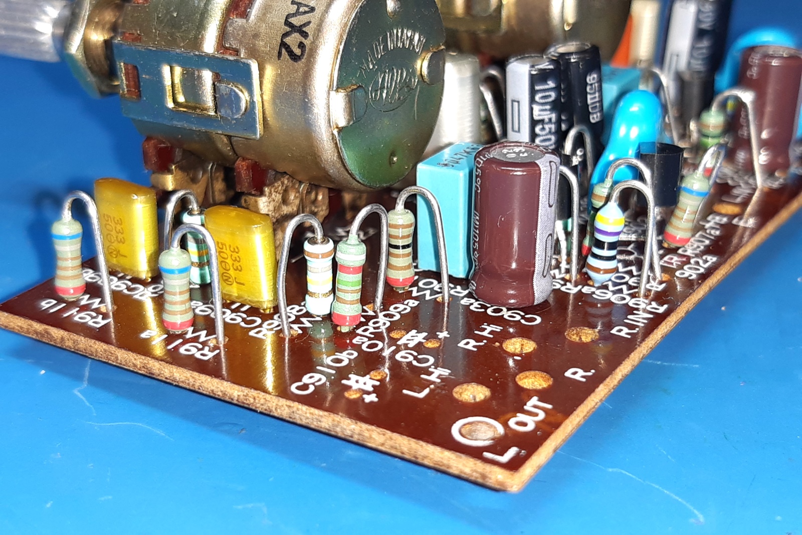
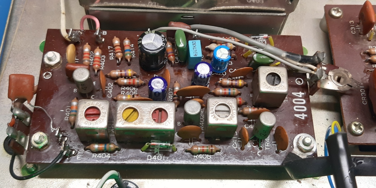
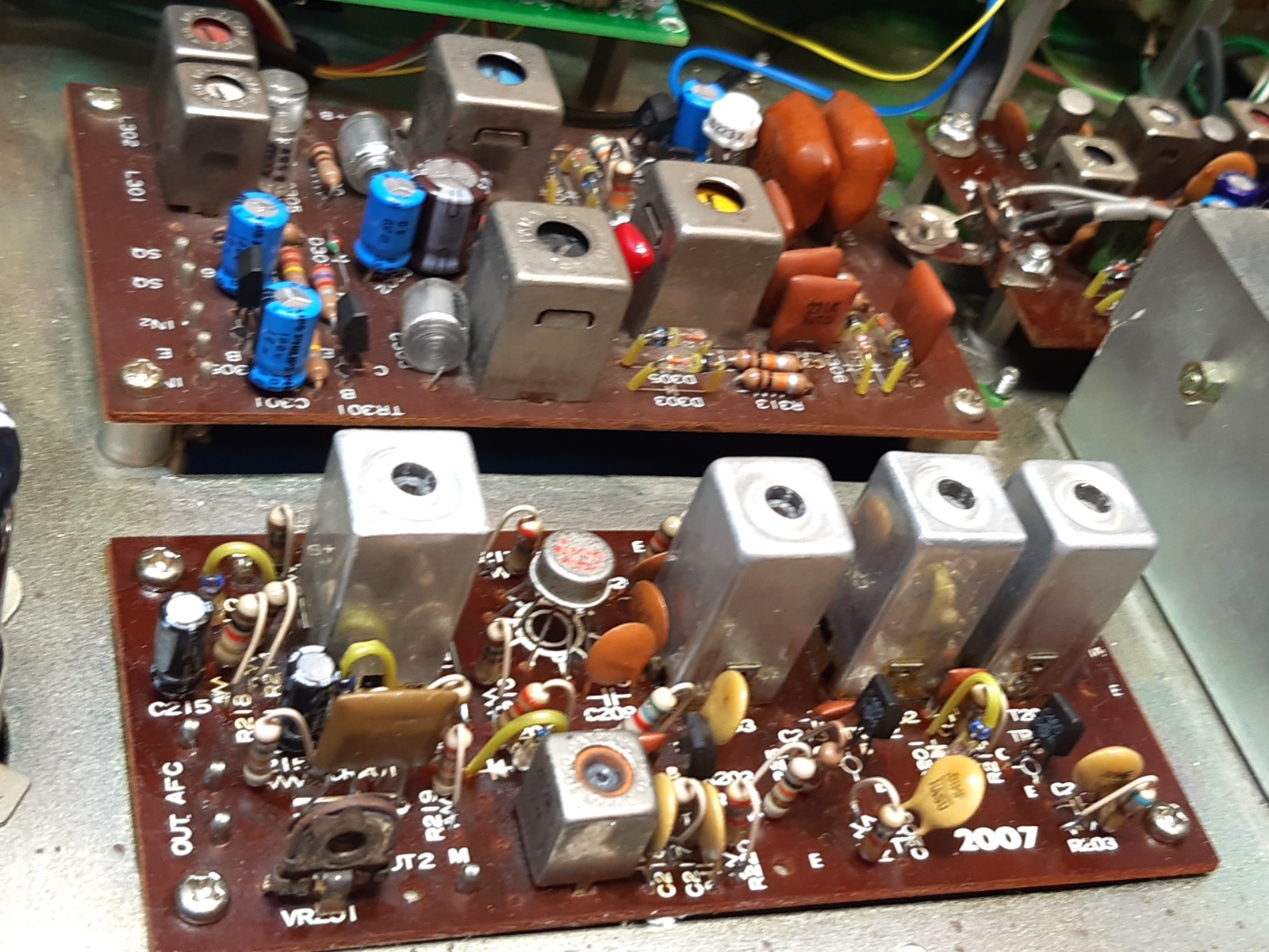
The tone amplifier board, called 9004
The tone amplifier had the old Hitachi transistors, as can be seen from their looks. Interesting too is the metal transistor on the most right picture almost on the most right hand side, this was a BC129B, a sign it was replaced many years ago when this part was around. apparently one of the 2SC458 transistors already failed in the old past.
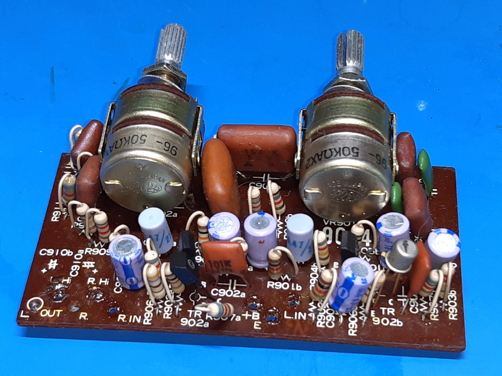
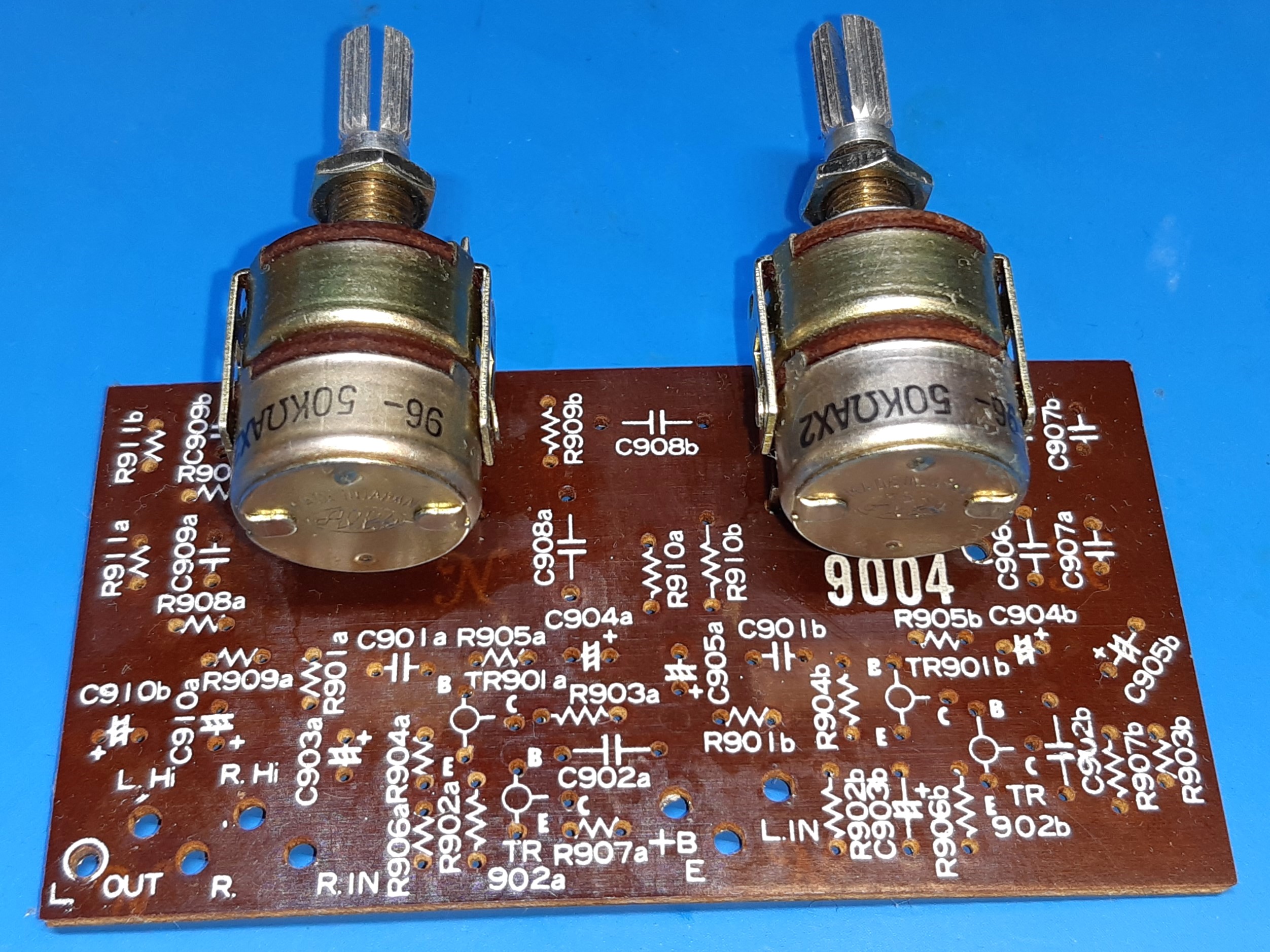
All parts were replaced, apart from the potentiometers. Fortunately, their operation is still perfect.
I used BC549 for the audio small signal transistor replacements.
R911=6k8 (it not clearly visible in the schematic. C906A/C907A have a wrong designation on the circuit card, the caps look interchanged, but they are on the right physical spot.
Read: "making too many pictures" DOES pay off, when removing ALL components from a circuit card!
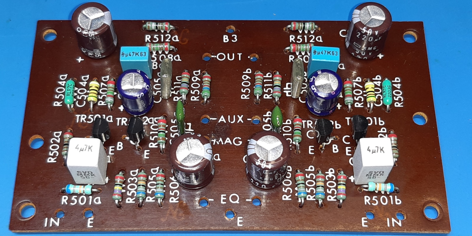
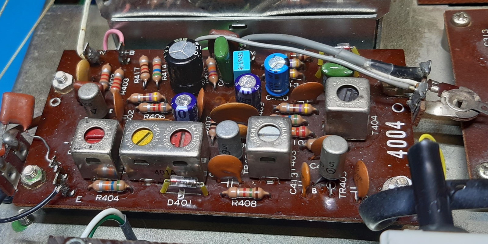
The EQU/AUX amplifier board, called F9005
Also here the always suspect Hitachi 2SC458 transistors were found. During test before demolishing, one second transistor appeared having 8 Volts, the other 12 VDC over it, so at least there was something wrong on this circuit card.
As I wanted to swipe all the parts off the card anyway, I did not investigate which transistor(s)acted up.
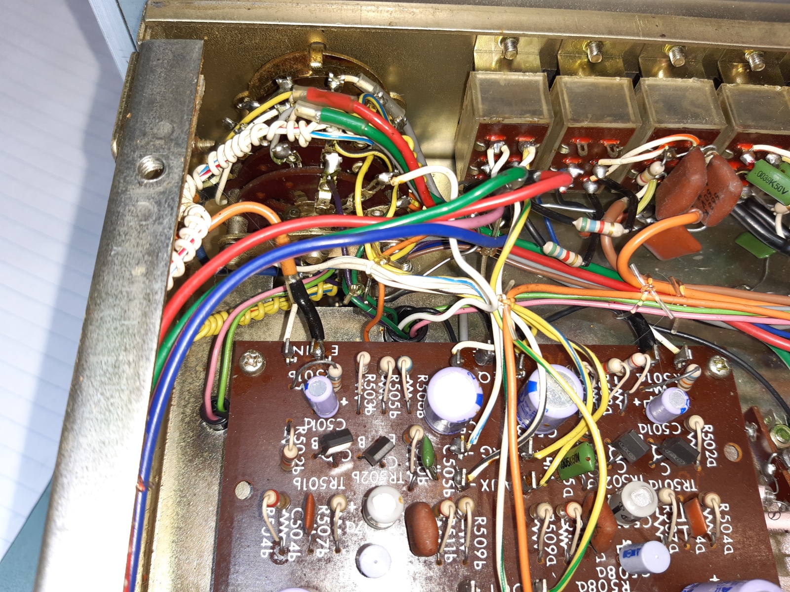
All parts were replaced. All resistors are high quality low noise metal film, of course. Coupling electrolytics, as on other places, I replaced using film capacitors.
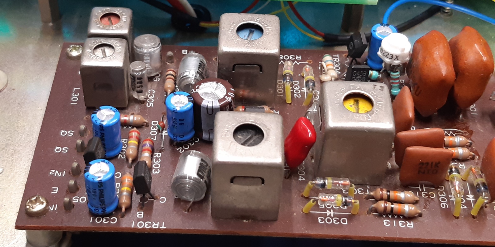
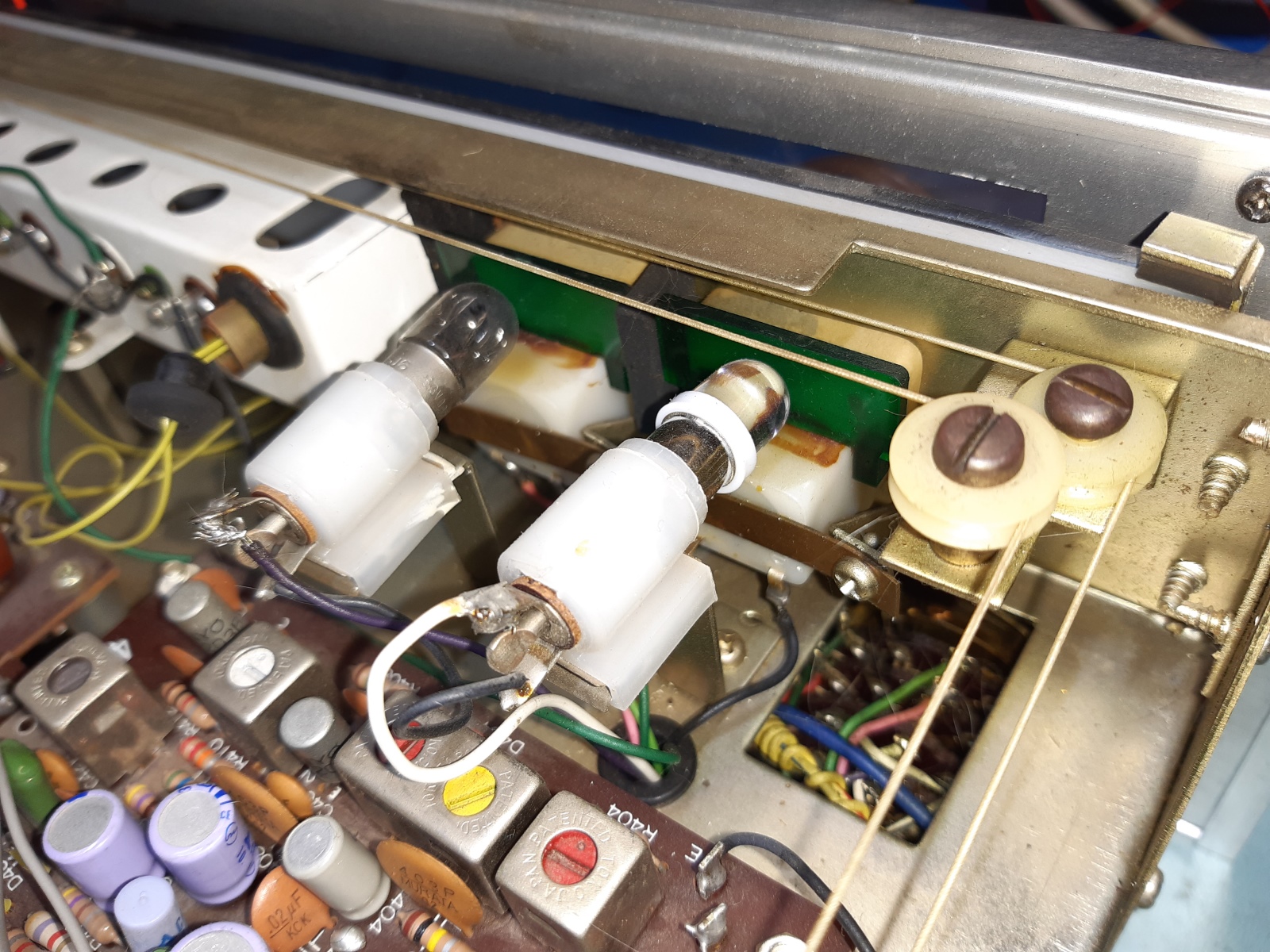
The Tuner boards.
The actual FM tuner front-end is a "3-gang" sealed one, I left it alone, btw:there are no electrolytic capacitors inside, and reception is good.
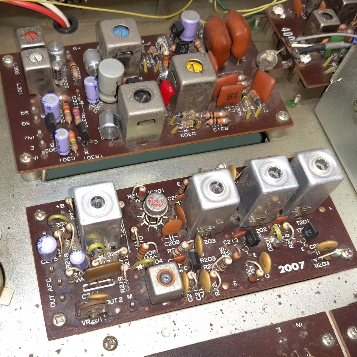
The tuner related IF / AM /stereo decoding circuit cards did get their aluminium electrolytic capacitors replaced.
The stereo lamp was replaced by a high brightness LED. I mounted a trimmer potentiometer onto two current limiting resistors, it is the white little trimmer. To avoid the LED being lit by any leakage current it is bypassed by a resistor. The trimmer allows for brightness adjustment.
The LED usage will also make sure the power supply transistor will generate less heat, supplying some 400 milliwatts less during stereo compared to the past.
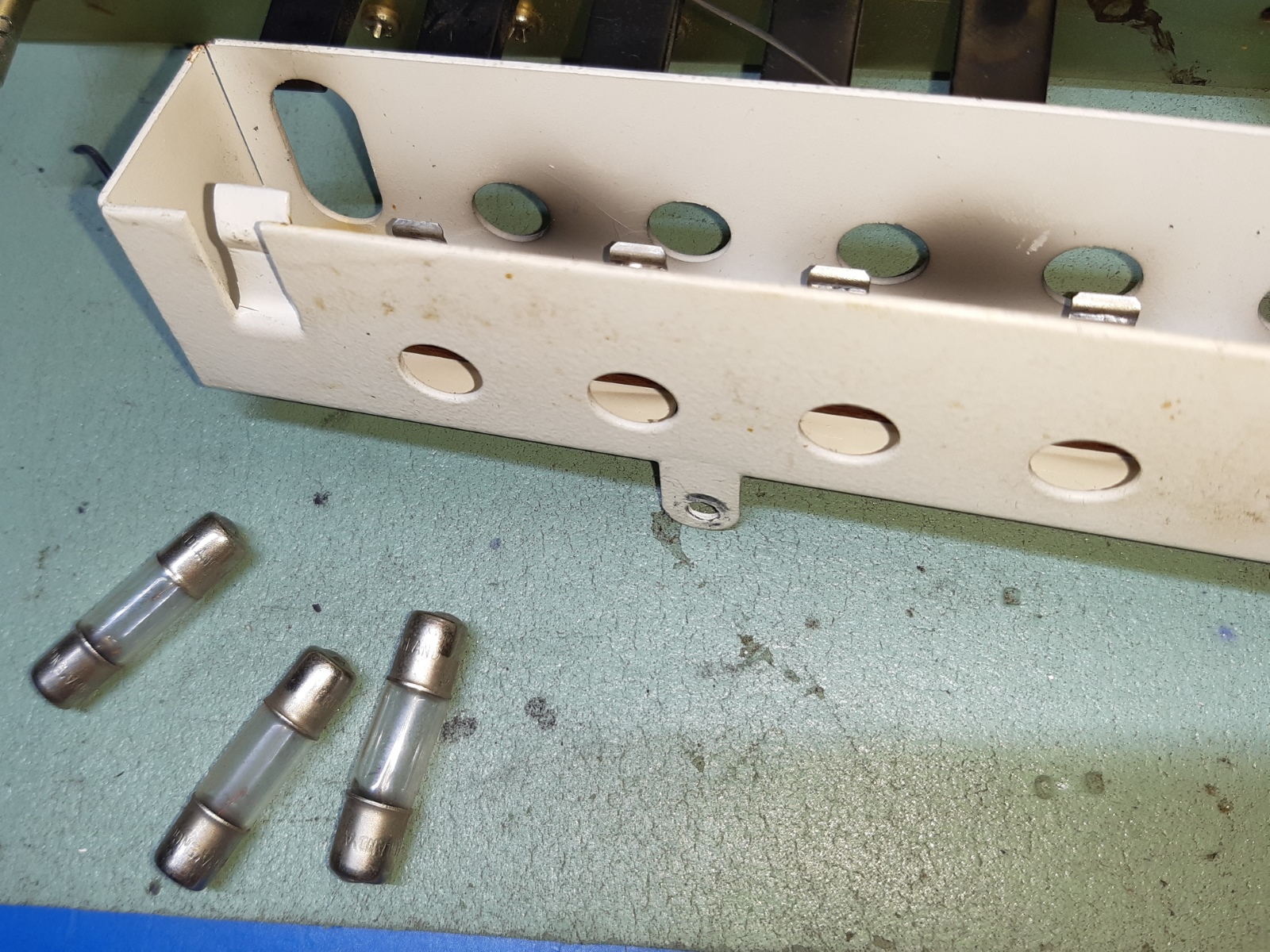
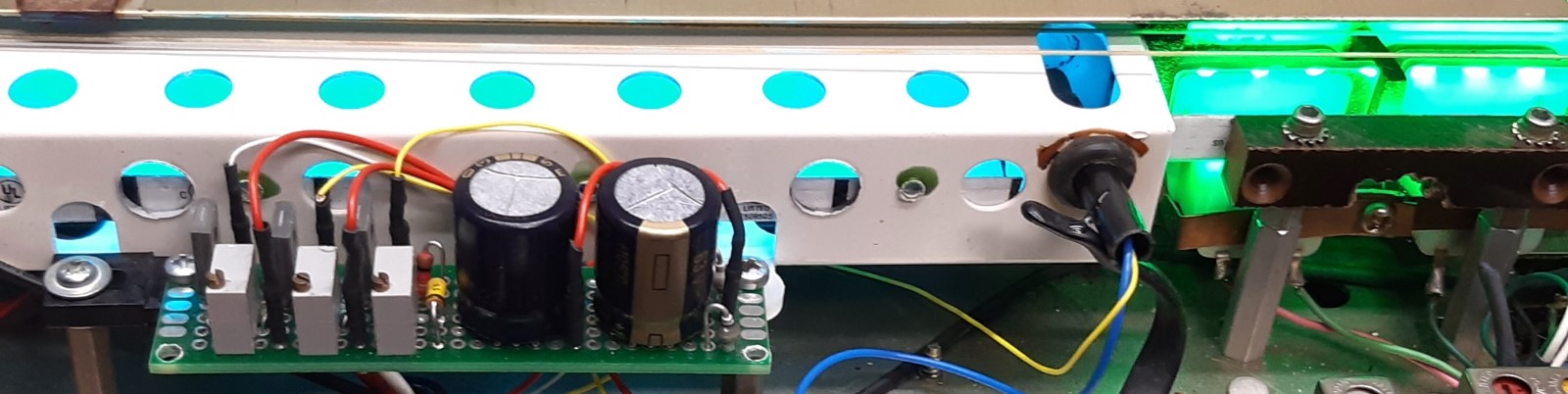
The receiver backlighting.
The scale backlighting was, in a bad shape, as expected.
The metering backlights consisted of one (blown) lamp and a LED one which gave some odd effect. Those lamps were switched depending on tuner selection (the left one) and FM selection (the meter on the right)

Below, find the new situation. I used a RGB strip. The meters did get a piece of strip powering the green part of the LED's only.
The scale lamps frame did get the blue and green led connected, so I needed a total of three current sources to steer the LED's for intensity.
The intensity of the lighting can now be adjusted, and for the scale backlight the greenish blue can be adjusted for hue between green and blue.
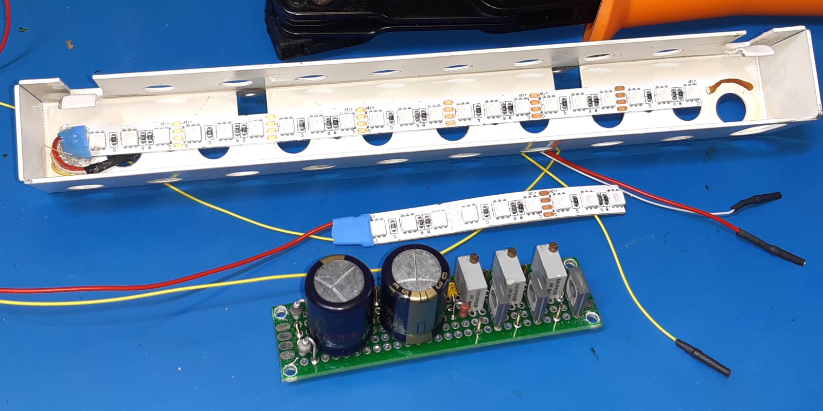
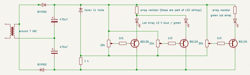
Next is the schematic I designed for the light steering stripboard and lightstrings.
The 6.5 Volts AC from the lighting output feed both a plus and a minus single rectifier diode, to be able to get some 15 Volts DC totally after rectification.
Experimentation showed some 10 Volts was more than enough to get an already very high brightness from the LED's. Therefore, an 11 Volts zener diode is aproppriate as a voltage limiter.
The 3 LED supply channels have detachable wiring to the LED strings, two for green and one for blue, each channel has its own trimming potentiometer for brightness.
The front of the receiver. It has some some of special look. In the end, I will sell it because of the "do you need all this equipment" thing.
The Back.
Ga naar Gerards homepage / go to Gerards main page ---->>> ![]()